1. Introduction
Membrane applications in water treatment have increased drastically in the global market due to advancements in materials and process improvements. Low-pressure membranes (microfiltration (MF) and ultrafiltration (UF)) have experienced widespread acceptance for municipal and industrial water treatment alongside conventional water treatment methods [
1,
2]. In the low-pressure membrane market, polymeric membranes dominate within water treatment but have shorter life spans (approx. 5–10 years) due to material degradation from exposure to conventional cleaning solutions [
3,
4]. Ceramic membranes represent an alternative choice for consideration due to their reported higher chemical, mechanical and thermal tolerances, better pore-size distribution, higher fluxes at lower pressures, and a longer effective lifespan offering greater functional advantages compared to polymeric membranes [
5,
6]. Research into ceramic membranes for water treatment applications is critical to ensure transition into utility systems with ease of implementation.
Control of reversible and irreversible fouling is critical for the operation of membrane systems. Deposition of natural organic matter (NOM) and other substances onto the surface of the membrane, which can be removed effectively through hydraulic backwashing, refers to reversible fouling. On the other hand, irreversible fouling refers to the adsorption or pore plugging of NOM and other substances either within the pores or on the surface of the membrane, which cannot be eliminated by hydraulic backwashing [
1,
7].
Chemical cleaning is primarily aimed at mitigating the loss in permeability from irreversible fouling and restoring the membrane flux. The membrane’s compatibility and feed characteristics are among the factors that determine what type of chemical solution should be used [
8]. Acid, alkali, oxidant, surfactant, and metal chelating agents are commonly employed cleaning agents [
8,
9,
10]. Sodium hypochlorite (NaOCl) and sodium hydroxide (NaOH) are the most commonly used chemicals for preserving and restoring membrane flux [
11]. These chemical solutions remove NOM fouling through oxidation, hydrolysis, and solubilization [
8]. NaOCl facilitates the breakdown of NOM functional groups into carboxyl and aldehyde groups, hence simplifying their removal from the surface, and sodium hydroxide (NaOH) has the ability to dissolve organic compounds such as proteins and polysaccharides [
6,
12].
Cleaning of membranes is primarily performed by using clean-in-place (CIP) protocols, which involve soaking a membrane in a chemical solution for 30 min to several hours, generally followed by solution circulation and subsequent flushing [
1,
13,
14]. In place of CIP, chemically enhanced backwash (CEB) protocols may be utilized to help control membrane fouling and delay the need for a CIP. CEB protocols employ the addition of lower concentrations of chemicals than a CIP process into a backwash cycle in place of the standard hydraulic backwash and can alleviate membrane fouling without removing the membrane from service [
12,
15]. Research into CEB protocols are somewhat limited and have been focused on more heavily within the polymeric fields [
12,
16,
17,
18].
In addition to traditional cleaning solutions, surfactants present a promising alternative for enhanced cleaning efficiency, versatility, and cost-effectiveness [
19,
20]. Surfactants form micelles at their critical micelle concentration (CMC) that abridge hydrophobic foulants, aiding their removal. These surfactants, combined with NaOH and NaOCl, may enhance cleaning by improving penetration within the foulant layer and facilitating chemical reactions that clean the membrane. Additionally, surfactants cause temporary changes to the characteristics of the membrane surface, reducing the forces that cause adhesion and limiting the reattachment of substances that cause fouling following the cleaning process [
21,
22,
23]. Previous studies have shown that combining surfactants with traditional cleaning agents improves cleaning performance and membrane longevity [
16,
24,
25,
26]. Levitsky et al. (2012) observed that the CEB of the combined cleaning solution, i.e. Tween 20 (a non-ionic surfactant), NaOCl, and NaOH effectively restored water flux at low chemical concentrations, resulting in reduced protein fouling on a polymeric PES membrane and no evidence of membrane disintegration [
16]. Gul et al. (2022) reported that a flat sheet PAN nanomembrane subject to a 24 h CIP soak with a binary solution of Triton + 5% NaOH demonstrated the highest flux recovery for the removal of engine oil wastewater compared to Triton or NaOH alone [
7]. Overall, research on combined cleaning solutions with surfactants is primarily focused on polymeric membranes.
Among non-ionic surfactants, Tween (a polysorbate-based surfactant) and Triton (an octylphenol ethoxylate-based surfactant) demonstrate distinct cleaning mechanisms that affect their efficacy in the removal of membrane fouling. Tween 80, a hydrophilic surfactant with a high hydrophilic-lipophilic balance (HLB), enhances fouling removal by reducing surface tension, improving membrane wettability, and facilitating the detachment of hydrophobic NOM components [
22,
27]. Conversely, Triton X-100, with its relatively lower HLB, interacts more strongly with hydrophobic foulants such as proteins, aiding in their emulsification and dispersion [
7,
28]. These differences influence the cleaning performance of chemically enhanced backwashing when used in combination with NaOH and NaOCl. Understanding the specific interactions between these surfactants and NOM foulants, such as humic acid (HA) and bovine serum albumin (BSA), is crucial for optimizing membrane cleaning protocols.
Research on surfactant-based cleaning, specifically on natural organic matter (NOM) fouling with CEB, and ceramic membranes, remains scarce. Thus, this research investigates the beneficial effect of utilizing a CEB protocol with non-ionic surfactants and conventional cleaning solutions for the removal of NOM foulants from ceramic UF membranes. This research assesses critical parameters such as transmembrane pressure, RIS fouling index, TOC mass balances, and permeability recovery. The current work systematically investigates the interactions between non-ionic surfactants and ceramic membranes and aims to enhance the recovery of membrane fouling; it also aims to develop a more effective and sustainable cleaning approach for UF ceramic membranes.
2. Materials and Methods
Model foulants: NOM model foulants used in this study were hydrophobic NOM, humic acid (Sigma Aldrich, St. Louis, MO, USA lot# BCCB6671) at 5 mg C/L, and hydrophilic protein, bovine serum albumin (BSA) (Sigma Aldrich, St. Louis, MO, USA) at 5 mg C/L. As reported in previous studies, humic acids and BSA were chosen due to their known fouling propensity and characteristics [
1,
15]. A 5 L feed water solution was prepared in DI water and mixed with a magnetic stirrer at 350 rpm for 24 h before each experiment to ensure complete dissolution. The feed water was adjusted to a pH of 7 ± 0.5 using H
3PO
4, and kaolin clay was added to achieve turbidity of 5 NTU, simulating moderate surface water conditions.
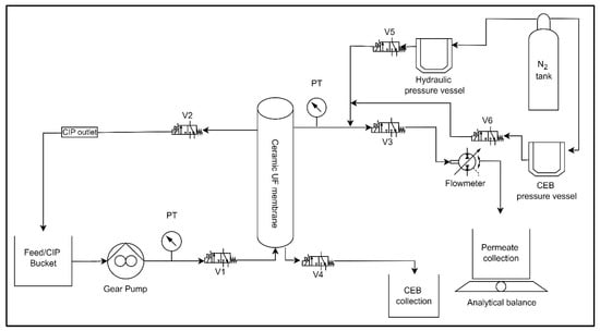
Bench-Scale experimental setup and operation: This study employed the use of an automated ceramic membrane system.
Figure 1 displays an illustration of the membrane system, including all the measuring instruments. The system consists of a digital gear pump (Cole Parmer: Drive no. 75211-30, Head no. 07003-04), a flow meter (101 Flo-Sen Mc Millan, 3T), solenoid valves (Macmaster: model no. 4711K731), two pressure transducers (OmegaDyne PX309-100G5V, PX409-030GUSB), and a pressure vessel (Cole Parmer: model no. 29902–90). Nitrogen gas was used to maintain pressure inside the pressure vessel throughout the backwash process. LabVIEW 2015 software (National Instruments, Texas, USA) was programmed to automate system processes. The system regulates the feed pump to maintain a constant flow rate, switches between filtration and backwash cycles, and logs real-time data on key operational parameters such as flow rate, pressure, and mass permeate. This study utilized a ceramic ultrafiltration (UF) membrane with a single channel. The membrane was manufactured by Atech Innovations and consisted of α-aluminum oxide (α-Al
2O
3) as the support material and zirconium dioxide (ZrO
2) as the membrane surface material.
Table 1 displays the attributes of the membrane utilized in the research.
The ceramic membrane was fouled with humic acid or BSA in a dead-end flow configuration. An initial flux of 100 L/m
2h was set for each experiment, which decreases as fouling increases, with data recorded by LabVIEW software. The fouling experiments involved 6 filtration cycles of 30 min with a 60 s backwash at 1 bar pressure after each filtration cycle. The TMP and flux data were logged every 30 s during tests using LabVIEW software. The flux measured during the fouling tests was standardized for temperature using Equation (1).
where Js and Jm represent the standardized and measured fluxes, respectively (L/m2h). Ts and Tm are the standard (i.e., 20 °C) and measured temperatures (°C) of the solution, respectively.
Clean water flux (CWF) values were monitored to stabilize baselines and maintain experiment reproducibility. Clean water was filtered through the membrane at flux steps of 100, 120, and 140 L/m
2h for 1 h, in 20 L/m
2h increments every 20 min. As the membrane fouls and moves away from the original CWF values, a clean-in-place (CIP) is conducted until it is within 25% of the original conditions. CIP protocol utilized a concentration of NaOH (460 mg/L) and NaOCl (500 mg/L) for 4 h, including two hours of solution recirculation and two hours of soaking [
1]. A CWF test was performed between trials to measure the membrane’s permeability (
Jsp). The standard flux (
Js) (L/m
2h) is divided by the differential pressure (Δ
P in bar) to obtain the clean membrane permeability.
Jsp was calculated using Equation (2).
Chemical Cleaning Experiments: This study examines the combination of surfactant, alkali, and oxidant as a cleaning agent to effectively manage the irreversible fouling of ceramic membranes caused by natural organic matter (NOM), as presented in
Table 2. The surfactants utilized in this investigation were Tween 80 and Triton X-100 (Sigma Aldrich, St. Louis, MO, USA). The critical micelle concentration (CMC) values for Tween 80 were reported as 0.015 mM [
29] and 0.26 mM Triton X-100 [
30]. In addition, the NaOH was obtained from Bioshop with a concentration of 98%
w/
v, while the NaOCl was acquired from Lavo (6%
w/
v). For CEB, the chemical solutions were prepared in deionized water by mixing a surfactant, an alkali (NaOH), and an oxidant (NaOCl), and for CIP, a mixture of alkali (NaOH) and an oxidant (NaOCl) was prepared in distilled water and utilized.
The combined chemicals contained in the 3-liter stainless-steel tank were subjected to 1 bar pressure using nitrogen gas. The backwash solution was injected into the membrane with an outside-in configuration at regular intervals of 30 min for 60 s, followed by a DI backwash pulse of 30 s to ensure the removal of surfactants from the membrane system. The cleaning efficacy was determined at the end of the experiment.
Contact angle and surface tension measurements: The wettability of a specific solution was evaluated by measuring the contact angle and surface tension of different cleaning solutions. The measurements were conducted at 22 ± 3 °C, using protocols from [
1]. The surface tension (λ) of the cleaning solutions was calculated using Jurin’s law (Equation (3)).
Figure 2 displays the contact angle and surface tension measurements of all the solutions.
where λ represents the surface tension of a liquid (N/m), h is the height of the capillary rise (m), ρ is the density of the CEB solution (kg/m3), g is the acceleration due to gravity (m/s2), r is the tube radius (m), and θ (theta) is the contact angle of the cleaning solution. The contact angle was determined by measuring it on a flat and smooth hydrophobic surface utilizing VCA Optima equipment. The measurement of capillary rise involved utilizing a slender stem of a clean glass Pasteur pipet; measurements were replicated seven times.
Carbon Mass Balance: The carbon mass balance across the membrane was determined by multiplying the total organic carbon (TOC) content (measured in mg/L) of the feed, permeate, and backwash solutions by their respective volumes (L). The efficacy of the cleaning method is determined by the quantity of carbon that remains on the membrane; a lesser mass of carbon indicates a more efficient cleaning process. The quantity of carbon present on the membrane was calculated using Equation (4).
Membrane Resistance-In-Series (RIS): To evaluate the membrane fouling, the clean membrane resistance (
Km), reversible fouling resistance (
Kr) and irreversible fouling resistance (
Kir) were calculated.
Km was derived from Equation (5) where Δ
P represents the change in transmembrane pressure (bar),
µ is the dynamic viscosity of water (kg/m·s) and
Js is the standard flux (typically 20 °C) (L/m
2h).
The measured flux and TMP from fouling tests were collected, analyzed, and corrected for temperature (
Js) (Equation (1)). After temperature adjustment, the resistance in series (RIS) (Equation (5)) model was used to estimate membrane reversible (
Kr, m
−1), irreversible (
Kir, m
−1), and total fouling resistances.
Kir and
Kr were combined to form the total fouling resistance,
Kf, where
Kf =
Kir +
Kr, during each filtration cycle. Thus, the overall resistance was expressed as
Kt =
Km +
Kf (in m
−1). Reversible and irreversible fouling resistance is determined by averaging four TMP and
Js values from the beginning and end of a filtration cycle.
The calculation of the decline of specific flux (%) was performed (Equation (6)) to assess the change in specific flux before and after the filtration test. This calculation employed the specific flux at the beginning of each filtration cycle (
Jsp Beg) and the specific flux at the end of the previous filtration cycle (
Jsp End) (Equation (7)).