1. Introduction
Traditional iterative location algorithms based on distance measurements are fast but often fail to account for system errors, affecting accuracy. This paper proposes a high-precision real-time distance difference localization algorithm based on LBL, leveraging error approximation from similar signal propagation paths under identical conditions. The main contributions of this study are as follows:
1. In complex marine environments, influenced by factors such as subsurface salinity, temperature, and ocean current changes, accurate modeling of systematic errors becomes a key challenge. In this paper, the sources of systematic errors in LBL positioning technology are systematically analyzed, and the influence mechanism of systematic errors on range-finder accuracy is described by establishing a detailed propagation model;
2. It reveals the limitations of traditional range iterative location algorithms and geometric analytic location algorithms when dealing with a large water area and complex environment. It is mainly reflected in the deduction of system errors and the layout geometry;
3. Guided by the concept of improving positioning accuracy, this paper innovatively proposes the strategy of converting LBL ranging information into distance difference information. Through the introduction of this technology, a high-precision real-time distance difference positioning algorithm based on LBL is successfully developed. After detailed accuracy analysis and verification, the algorithm has significant advantages and application potential in providing real-time high-precision positioning information.
2. Error Modeling of Underwater LBL Measurement System
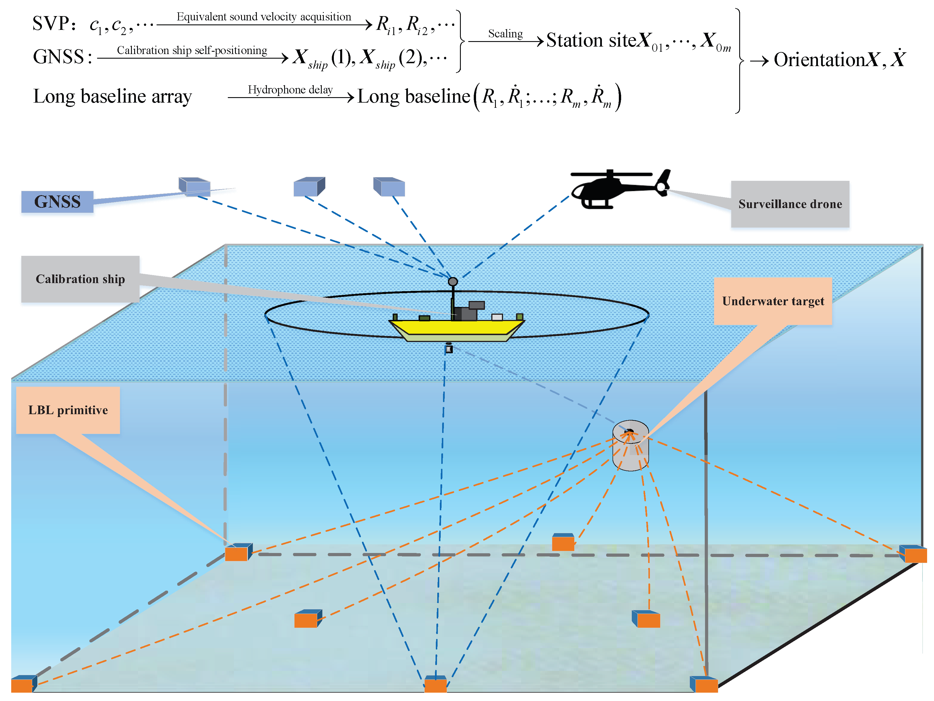
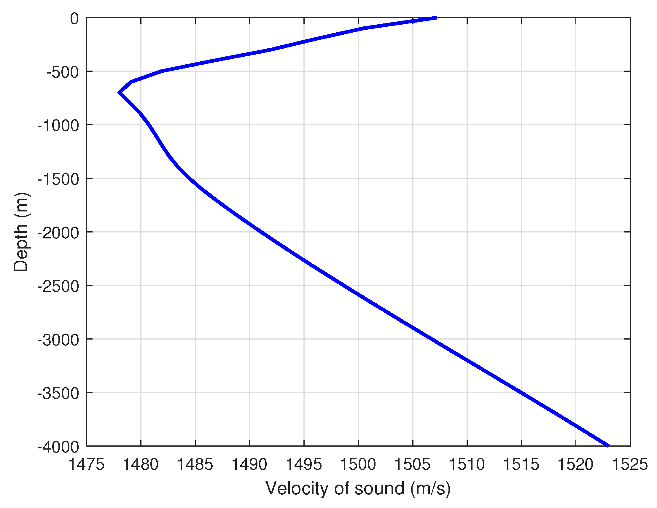
(1) Sound Velocity Acquisition: This preliminary step is crucial for accurate positioning and is completed before the main positioning task. It involves utilizing a sound velocity profile (SVP) to measure the speed of sound at various water depths. The measurements, denoted as , represent sound velocities at corresponding depths. For the purpose of the positioning calculations, the equivalent sound velocity is often determined by averaging these measurements, providing a representative value for the environment.
(2) LBL Calibration: This step, conducted prior to positioning, is essential for ensuring the accuracy of the LBL system. The calibration process begins with using a GNSS receiver to determine the precise location of the calibration ship. These GNSS data yield the ship’s exact position and provide the address of the calibration station. LBL hydrophones, which are fixed to the seafloor, are then calibrated based on the GNSS-derived location of the ship and the measured distance from the ship to the first LBL hydrophone. This calibration process results in accurate coordinates for underwater LBL stations, denoted as .
(3) Target Positioning: This step is executed in real-time or according to the timing requirements of the positioning task. Utilizing calibrated LBL stations, the system measures the distance from the target to each LBL station. By integrating the data from the hydrophones and the calibrated LBL stations, the system can also track changes in the distance between the target and the LBL stations, allowing for precise and dynamic positioning of the target within the monitored area.
In practical applications, the LBL positioning system is interfered with by many kinds of errors, which directly affect the stability and accuracy of positioning accuracy. Therefore, in-depth analysis of the sources and characteristics of these errors has become a crucial step to improve positioning accuracy. The error sources include but are not limited to the multipath effect in the underwater acoustic propagation path, the spatiotemporal variation of the acoustic velocity profile, the underwater acoustic sensor calibration error, and the calculation error of the solution model itself. Each error has its specific physical background and mathematical expression. In this section, the error modeling of the LBL positioning system is carried out through detailed analysis, which provides a basis for the subsequent improvement of the LBL positioning algorithm.
2.1. Timing System Error
2.2. Sound Velocity System Error
2.3. Refraction System Error
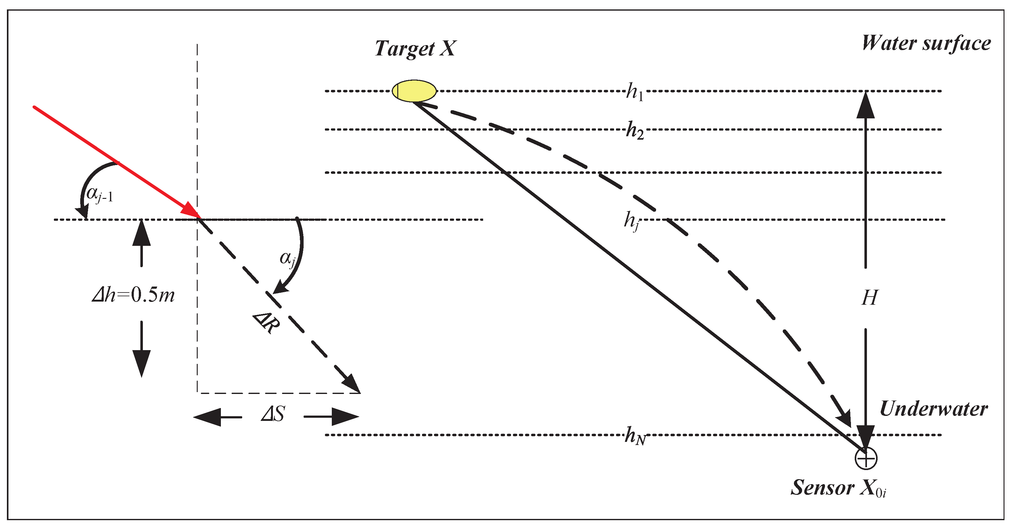
where c represents the underwater speed of sound. If a sound velocity profile, denoted as , is obtained, the sound velocity c used in Equation (11) can be computed using the weighted sound velocity method.
where H is the total depth (see the schematic diagram of the underwater acoustic profile), is the depth of the j-th layer, and is the sound velocity value of the j-th layer. In particular, if , then the following is true:
The sound velocity profiler can measure the depth and sound velocity of the layered medium, and the measurement accuracy of sound velocity is recorded as . If the initial grazing angle cosine and vertical distance H are known, the refraction path, the total length of the broken line R, and the horizontal distance S can be obtained by the algorithm.
2.4. Site Error of Standard School Station
2.5. Comprehensive Error Model
The equivalent ranging errors caused by system errors are divided into the following three types:
The above equation shows that the equivalent error is composed of systematic error related to distance, depth, and constant systematic error.
3. Limitation Analysis of the Traditional Algorithm
3.1. Range Iterative Positioning the Algorithm and Its Limitations
In short, the overall observation geometry of the range iterative legal location algorithm is better, but the extreme observation geometry is worse. However, this algorithm does not consider the deduction of systematic error, which leads to a large final positioning error. In order to overcome the problem of systematic error deduction, the geometric analytic positioning algorithm is introduced below.
3.2. Geometric Analytic Positioning Algorithm and Its Limitations
The geometric analytic positioning algorithm can use the subtraction of and to deduct most of the system errors, but the limitation of the algorithm is that all the stations are on the seabed, the configuration of the stations is almost coplanar, and the geometry of the stations is poor, resulting in a large number of conditions in matrix , and the positioning results are very unstable.
In summary, while the geometric analytic algorithm employs a non-iterative linear solution approach, which offers rapid computation and utilizes the square difference method to substantially mitigate the impact of systematic errors on positioning, it is still hindered by its sensitivity to measurement errors and the geometric configuration of the layout. This sensitivity, exacerbated by the planar arrangement, results in compromised positioning accuracy. To address these limitations, particularly the challenges associated with systematic error correction, geometric flatness under extreme observation conditions, and suboptimal geometry inherent to the geometric analytic method, this paper introduces a novel distance difference positioning algorithm. This new algorithm is specifically designed to overcome these issues, providing a more robust solution for accurate positioning by minimizing the influence of both systematic errors and adverse geometric conditions.
4. A Novel Distance Difference Iterative Localization Algorithm and Its Accuracy Analysis
4.1. Distance Difference Equation and Its Iterative Process
4.2. Precision Analysis of the Distance Difference Iterative Localization Algorithm
where the error vector of the distance difference is , the station address error caused by the inaccurate calibration of underwater acoustic elements is , and is a quasi-diagonal matrix composed of the direction vector, which satisfies the following:
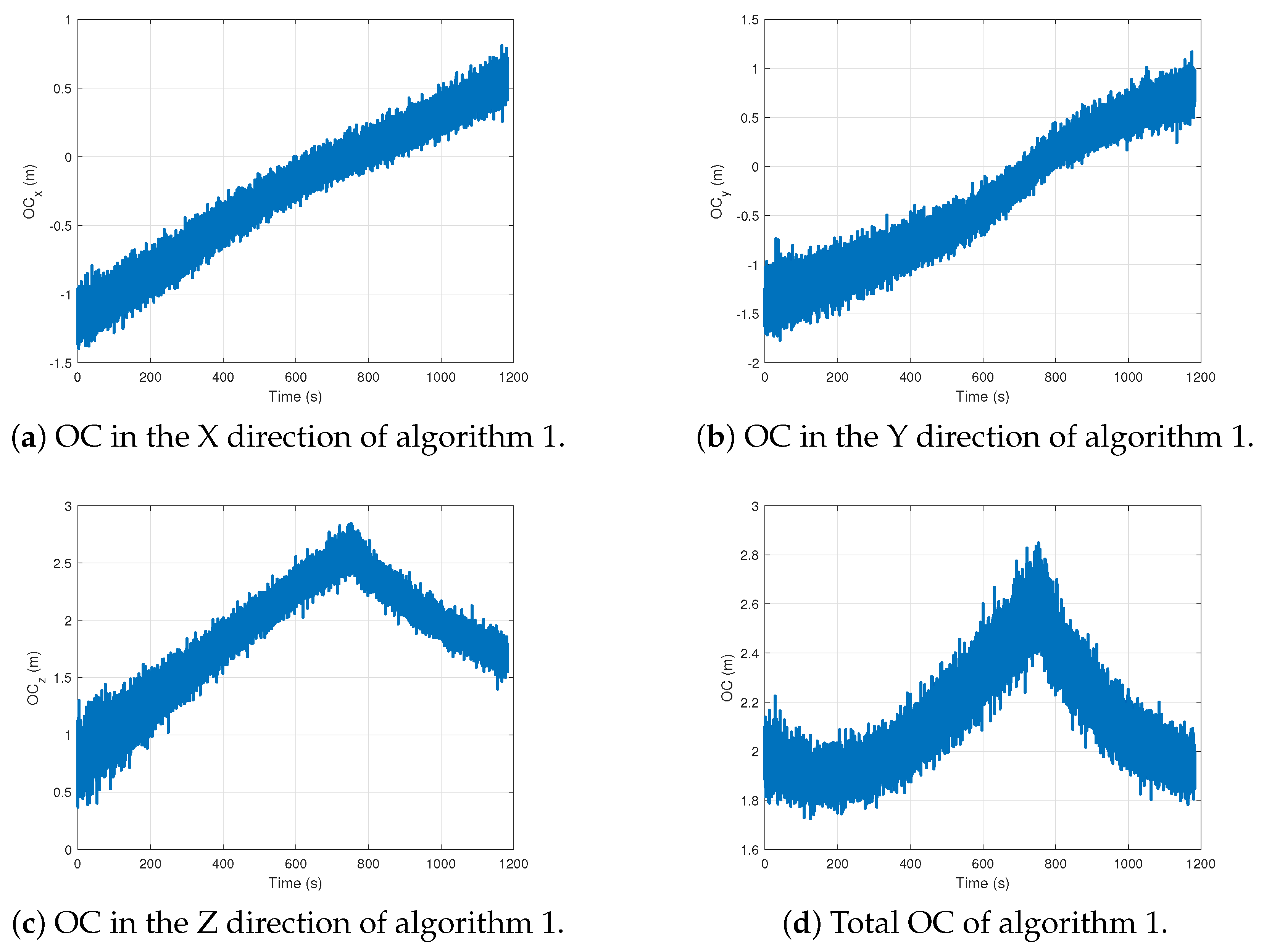
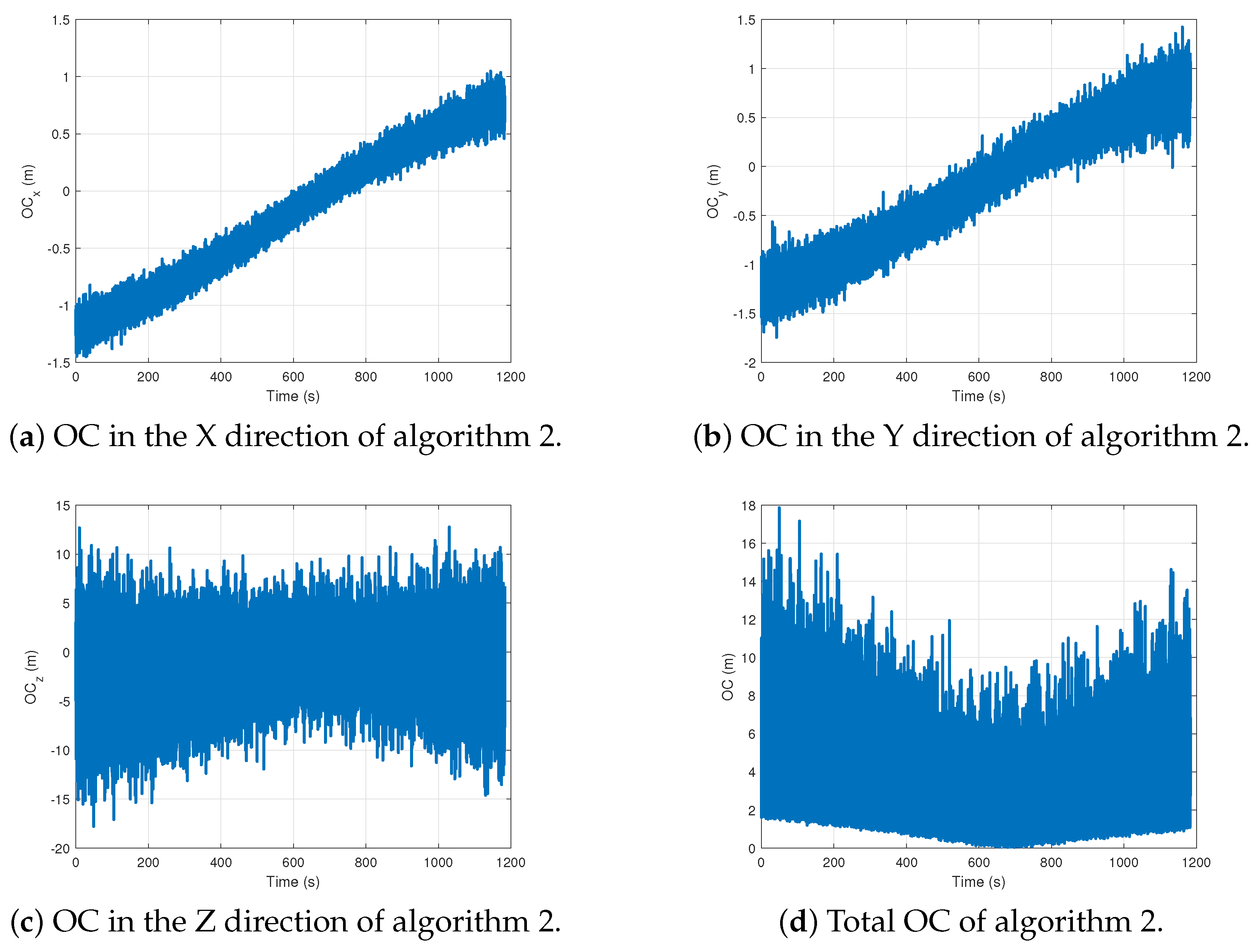
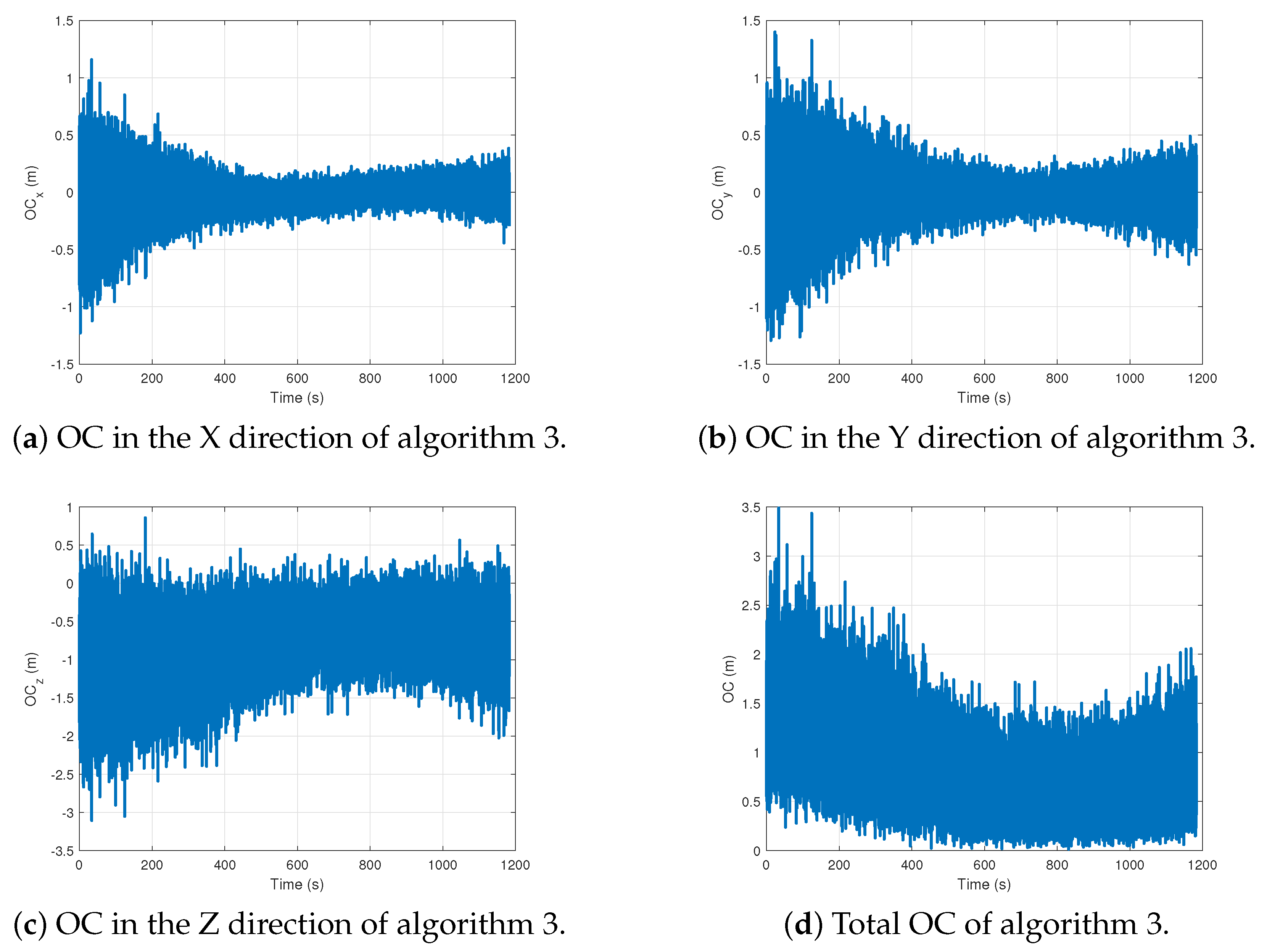
The iterative positioning algorithm for LBL distance measurement is algorithm 1, the geometric analytic positioning algorithm for LBL is algorithm 2, and the distance difference positioning algorithm based on LBL proposed in this paper is algorithm 3. The essential steps of the algorithm introduced in this article are outlined in Algorithm 3.
| Algorithm 3 Precision analysis of the distance difference iterative localization algorithm |
Input: , m, e; Output: ;
|
This implies that the distance difference approach effectively mitigates the majority of systematic errors inherent in traditional positioning methods. By leveraging this technique, the algorithm can avoid scenarios where the layout geometry approaches coplanarity, and the observation geometry encounters extreme conditions. Consequently, the proposed LBL distance difference iterative positioning algorithm offers substantial improvements over conventional algorithms. It addresses and overcomes their inherent limitations, thereby achieving enhanced positioning accuracy. This advancement is particularly notable in environments where precision is critical, as it reduces susceptibility to errors and enhances overall reliability in positioning applications.
5. Numerical Simulation
5.1. Simulation Design
The element error is considered in the simulation experiment condition, and the site error is not considered. Among them, the measured error includes random error and systematic error. The random error of the probe error follows the normal distribution with a mean of 0 and a standard deviation of 0.1 m, and the constant systematic error is 1 m. The systematic error varying with distance and grazing Angle is positively correlated with water depth and propagation distance, with a maximum of 1 m.
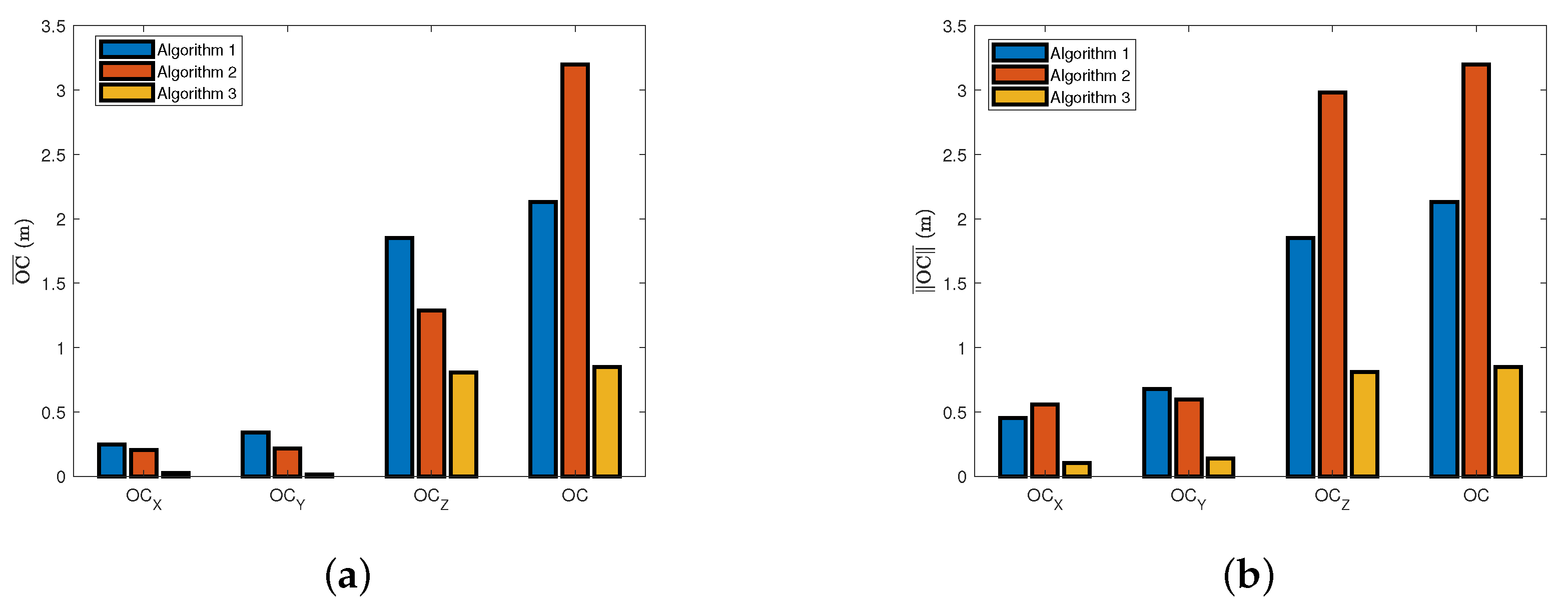
The observed residual (OC) is the difference between observed values and calculated values, which can be used as an index to measure the difference between the predicted value and the real value of the model, which can effectively measure the prediction deviation of the model at different data points and intuitively express the accuracy of the algorithm. In this paper, OC is used as the performance criterion of the algorithm.
5.2. Simulation Results
Take 20 sampling points near the task point (14991–15010 sampling points) of UUV underwater navigation, and carry out a comparative analysis of errors of various algorithms. Let be the errors in all directions and the total errors of algorithm 1, algorithm 2, algorithm 3, with similar naming rules.
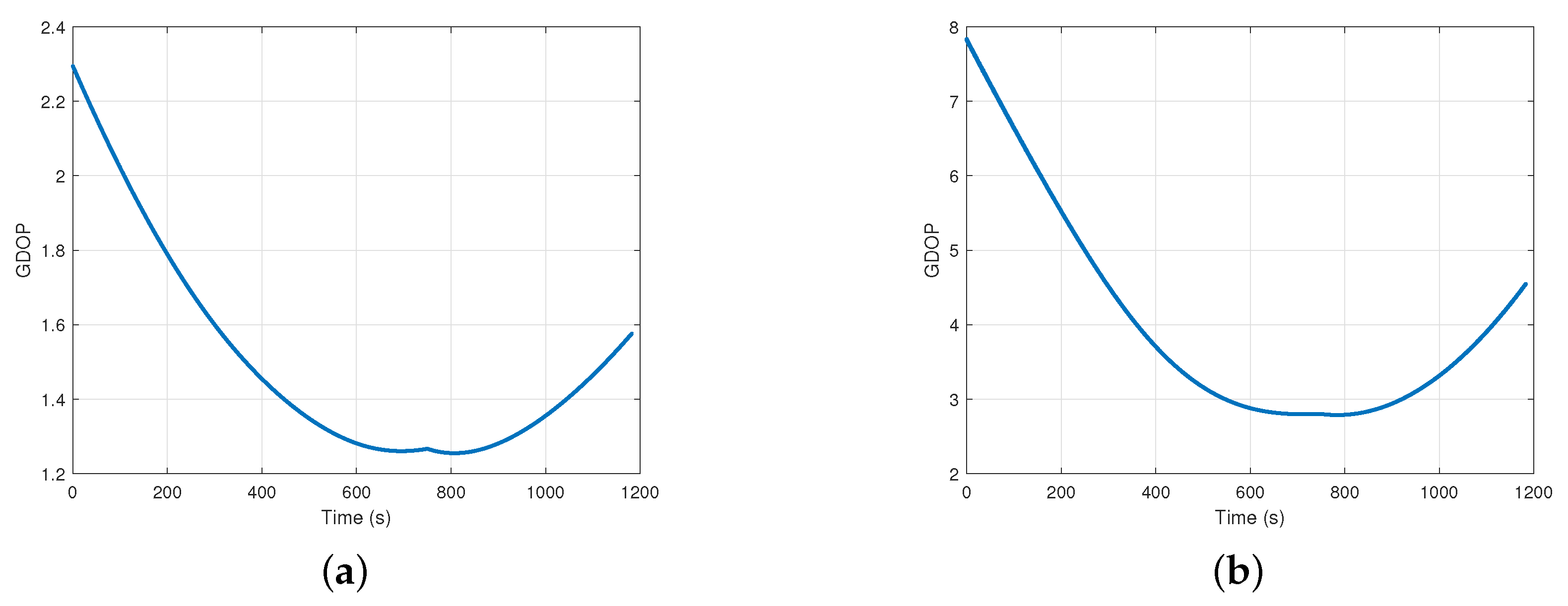
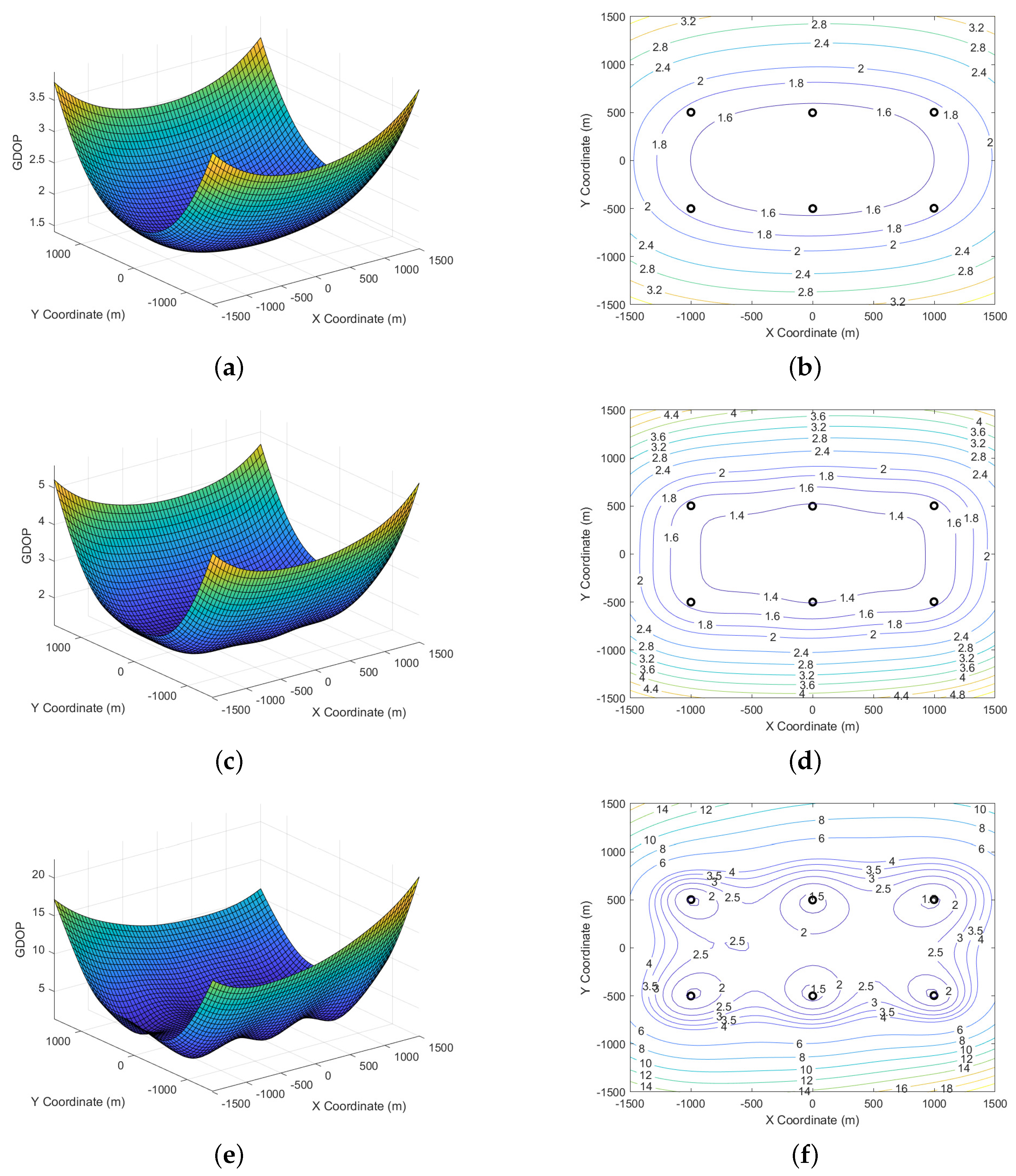
The observed discrepancies in accuracy at certain sampling points for the proposed algorithm, compared to algorithm 2, are analyzed further under the experimental conditions. This analysis incorporates the examination of GDOP variation trends relative to UUV motion in both range-ranging and range-difference positioning systems. Such an examination provides a deeper understanding of the positional accuracy variations and underscores the need for continuous refinement of positioning algorithms to address systematic errors and optimize performance in practical applications.
Further analysis under the experimental conditions clarifies why some sampling points of the proposed algorithm exhibit less accuracy than algorithm 2. This examination includes the evaluation of GDOP variation trends for range and distance difference positioning systems relative to UUV motion.
6. Conclusions
The complex marine environment poses significant challenges for underwater LBL positioning due to systematic errors that affect sound wave propagation, leading to lower accuracy in traditional distance measurement methods. Traditional geometric analysis positioning algorithms often struggle with high sensitivity to measurement errors, especially when the station layout is close to a planar configuration. In response to these challenges, this article introduces a novel systematic error model for underwater LBL measurements and proposes a high-precision, real-time distance difference positioning algorithm. The theoretical accuracy analysis and numerical simulations demonstrate that the proposed algorithm has reduced geometric layout requirements compared to conventional LBL positioning methods. This algorithm effectively accommodates station layouts on relatively flat seabed terrains, mitigates system errors, and enhances real-time positioning accuracy.
The main contributions of this work are the development of a systematic error model and a new distance difference positioning algorithm that offers improved accuracy and flexibility in various underwater acoustic positioning scenarios. The potential applications of this research extend to real-world underwater acoustic positioning systems, where improved accuracy and adaptability can enhance operational efficiency and reliability. To further enhance precision, we propose several future research directions:
1. Integration of surface sensors: Incorporating sensors on the water surface could mitigate geometric layout discrepancies, thereby improving the overall accuracy of positioning systems, especially in the Z-direction.
2. Development of a spline-based EMBET algorithm: Introducing spline-based error minimization based on an error tracking (EMBET) algorithm could advance error detection and correction capabilities, leading to more accurate positioning.
3. Utilization of visualized volume accuracy condition numbers: Leveraging visualized volume accuracy condition numbers can optimize path planning and decision-making processes. This approach has the potential to enhance the system’s adaptability and performance across diverse underwater environments.
These proposed approaches offer promising avenues for future research and development, aiming to refine positioning accuracy and system effectiveness in complex aquatic settings.
Author Contributions
Conceptualization, data curation, formal analysis, investigation, methodology, software, validation, visualization, writing—original draft, writing—review and editing, H.C.; conceptualization, formal analysis, investigation, methodology, project administration, supervision, writing—original draft, writing—review and editing, Z.H.; funding acquisition, project administration, resources, supervision, writing—review and editing, J.W.; project administration, supervision, X.Z.; project administration, supervision, writing—review and editing, B.H. All authors have read and agreed to the published version of the manuscript.
Funding
This work was supported by the National Natural Science Foundation of China (No. 62203458) 396 and the National Key R&D Program of China (No. 2020YFA0713502).
Institutional Review Board Statement
Not applicable.
Informed Consent Statement
Not applicable.
Data Availability Statement
Data are contained within the article.
Conflicts of Interest
The authors declare no conflicts of interest.
References
- Xing, Y.; He, Z.; Wang, J.; Zhou, X.; Chen, Y.; Pan, X. TOA positioning algorithm of LBL system for underwater target based on PSO. J. Syst. Eng. Electron. 2023, 34, 1319–1332. [Google Scholar]
- Lu, Y.; Wang, J.; Zhou, H.; Wang, D.; Xing, Y.; He, Z. Station layout optimization for underwater acoustic positioning system based on combined cone configuration. Ocean Eng. 2024, 294, 116753. [Google Scholar] [CrossRef]
- Lan, H.; Lv, Y.; Jin, J.; Li, J.; Sun, D.; Yang, Z. Acoustical Observation With Multiple Wave Gliders for Internet of Underwater Things. IEEE Internet Things J. 2021, 8, 2814–2825. [Google Scholar] [CrossRef]
- Zhu, L.; Liu, Y.; He, D.; Guan, K.; Ai, B.; Zhong, Z.; Liao, X. An efficient target detection algorithm via Karhunen-Loève transform for frequency modulated continuous wave (FMCW) radar applications. IET Signal Proc. 2022, 16, 800–810. [Google Scholar] [CrossRef]
- Yang, Y.; Wang, X.; Wu, X.; Lan, X.; Su, T.; Guo, Y. A Robust Target Detection Algorithm Based on the Fusion of Frequency-Modulated Continuous Wave Radar and a Monocular Camera. Remote Sens. 2024, 16, 2225. [Google Scholar] [CrossRef]
- Tianyi, C.; Bo, D.; Weibo, H. Super-resolution parameter estimation of monopulse radar by wide-narrowband joint processing. J. Syst. Eng. Electron. 2023, 34, 1158–1170. [Google Scholar] [CrossRef]
- Paull, L.; Saeedi, S.; Seto, M.; Li, H. AUV navigation and localization: A review. IEEE J. Ocean. Eng. 2014, 39, 131–149. [Google Scholar] [CrossRef]
- Zhang, J.; Han, Y.; Zheng, C.; Sun, D. Underwater target localization using LBL positioning system. J. Appl. Acoust. 2016, 111, 129–134. [Google Scholar] [CrossRef]
- Sun, D.; Li, H.; Zheng, C.; Li, X. Sound velocity correction based on effective sound velocity for underwater acoustic positioning systems. Appl. Acoust. 2019, 151, 55–62. [Google Scholar] [CrossRef]
- Han, Y.; Zhang, J.; Sun, D. Error control and adjustment method for underwater wireless sensor network localization. Appl. Acoust. 2018, 130, 293–299. [Google Scholar] [CrossRef]
- Han, Y.; Li, Z.; Zheng, C.; Sun, D. A precision evaluation method of USBL positioning systems based on LBL triangulation. Acta Phys. Sin. 2015, 64, 094301. [Google Scholar]
- Sun, D.; Ding, J.; Zheng, C.; Huang, W. An Underwater Acoustic Positioning Algorithm for Compact Arrays with Arbitrary Configuration. IEEE J. Sel. Top. Signal Process. 2019, 13, 120–130. [Google Scholar] [CrossRef]
- Tan, H.-P.; Diamant, R.; Seah, W.K.G.; Waldmeyer, M. A survey of techniques and challenges in underwater localization. Ocean Eng. 2011, 38, 1663–1676. [Google Scholar] [CrossRef]
- Batista, P.; Silvestre, C.; Oliveira, P. A Sensor-based LBL Position and Velocity Navigation Filter for Underwater Vehicles. IFAC Proc. Vol. 2010, 43, 302–307. [Google Scholar] [CrossRef]
- Jin, S.; Wang, J.; Park, P.-H. An improvement of GPS height estimations: Stochastic modeling. Earth Planets Space 2005, 57, 253–259. [Google Scholar] [CrossRef]
- Yeh, T.-K.; Chen, C.-H.; Xu, G.; Wang, C.-S.; Chen, K.-H. The Impact on the Positioning Accuracy of the Frequency Reference of a GPS Receiver. Surv. Geophys. 2013, 34, 73–87. [Google Scholar] [CrossRef]
- Yan, W.; Chen, W.; Cui, R. Moving LBL positioning algorithm with uncertain sound speed(Article). J. Mech. Sci. Technol. 2015, 29, 3995–4002. [Google Scholar] [CrossRef]
- Yan, W.; Chen, W.; Cui, R.; Li, H. Optimal distance between mobile buoy and target for moving LBL positioning system. J. Navig. 2015, 68, 809–826. [Google Scholar] [CrossRef]
- Gao, W.; Gao, C.; Pan, S. A method of GPS/BDS/GLONASS combined RTK positioning for middle-LBL with partial ambiguity resolution. Surv. Rev. 2017, 49, 212–220. [Google Scholar] [CrossRef]
- Sun, D.; Gu, J.; Han, Y.; Zhang, J. Inverted ultra-short baseline signal design for multi-AUV navigation. Appl. Acoust. 2019, 150, 5–13. [Google Scholar] [CrossRef]
- Wang, Y.; Yang, X.; Hao, L.; Li, T.; Chen, C.L. Integral Sliding Mode Output Feedback Control for Unmanned Marine Vehicles Using T–S Fuzzy Model with Unknown Premise Variables and Actuator Faults. J. Mar. Sci. Eng. 2024, 12, 920. [Google Scholar] [CrossRef]
- Hao, L.-Y.; Zhang, H.; Li, T.-S.; Lin, B.; Chen, C.L.P. Fault Tolerant Control for Dynamic Positioning of Unmanned Marine Vehicles Based on T-S Fuzzy Model With Unknown Membership Functions. IEEE Trans. Veh. Technol. 2021, 70, 146–157. [Google Scholar] [CrossRef]
- Hao, L.-Y.; Wang, R.-Z.; Shen, C.; Shi, Y. Trajectory Tracking Control of Autonomous Underwater Vehicles Using Improved Tube-Based Model Predictive Control Approach. IEEE Trans. Ind. Inform. 2023, 20, 5647–5657. [Google Scholar] [CrossRef]
- Gao, X.; Li, T. Dynamic Positioning Control for Marine Crafts: A Survey and Recent Advances. J. Mar. Sci. Eng. 2024, 12, 362. [Google Scholar] [CrossRef]
- He, Z.; Zeng, K.; Wei, C.; Xu, H.; Xiang, S.; Wang, J. Underwater multi-baseline single beacon system. In Remote Sensing Data Real-Time and Post-Processing Methods; Li, J., Jia, X., Eds.; Science Press: Washington, DC, USA, 2024; pp. 146–173. (In Chinese) [Google Scholar]
- Xing, Y.; Wang, J.; He, Z.; Chen, Y.; Zhou, X. An Identification Method of LBL Underwater Posi-tioning Systematic Error with Optimal Selection Criterion. Sci. Rep. 2024, 14, 21462. [Google Scholar] [CrossRef]
- Xing, Y.; Wang, J.; Hou, B.; He, Z.; Zhou, X. Underwater Long Baseline Positioning Based on B-Spline Surface for Fitting Effective Sound Speed Table. J. Mar. Sci. Eng. 2024, 12, 1429. [Google Scholar] [CrossRef]
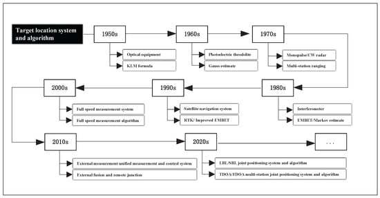
Target location system and algorithm development diagram.
Figure 1.
Target location system and algorithm development diagram.
Interactive schematic of underwater LBL acoustic positioning.
Figure 2.
Interactive schematic of underwater LBL acoustic positioning.
Refraction diagram of a sound wave.
Figure 3.
Refraction diagram of a sound wave.
Underwater acoustic profile.
Figure 4.
Underwater acoustic profile.
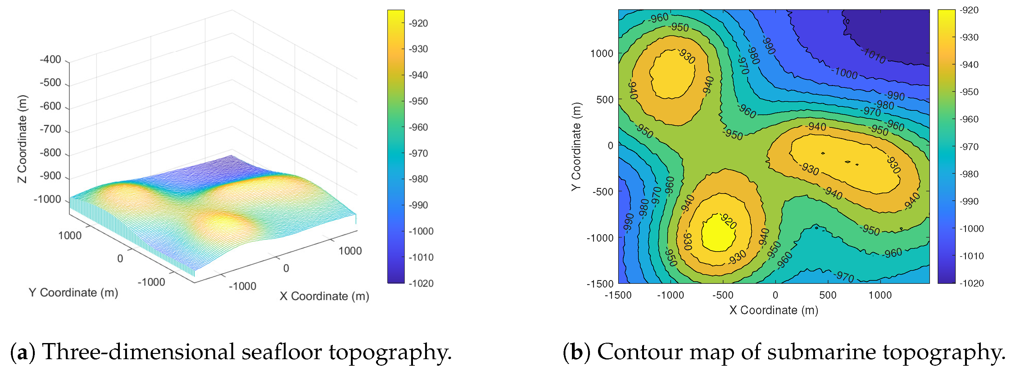
Simulated submarine topographic map.
Figure 5.
Simulated submarine topographic map.
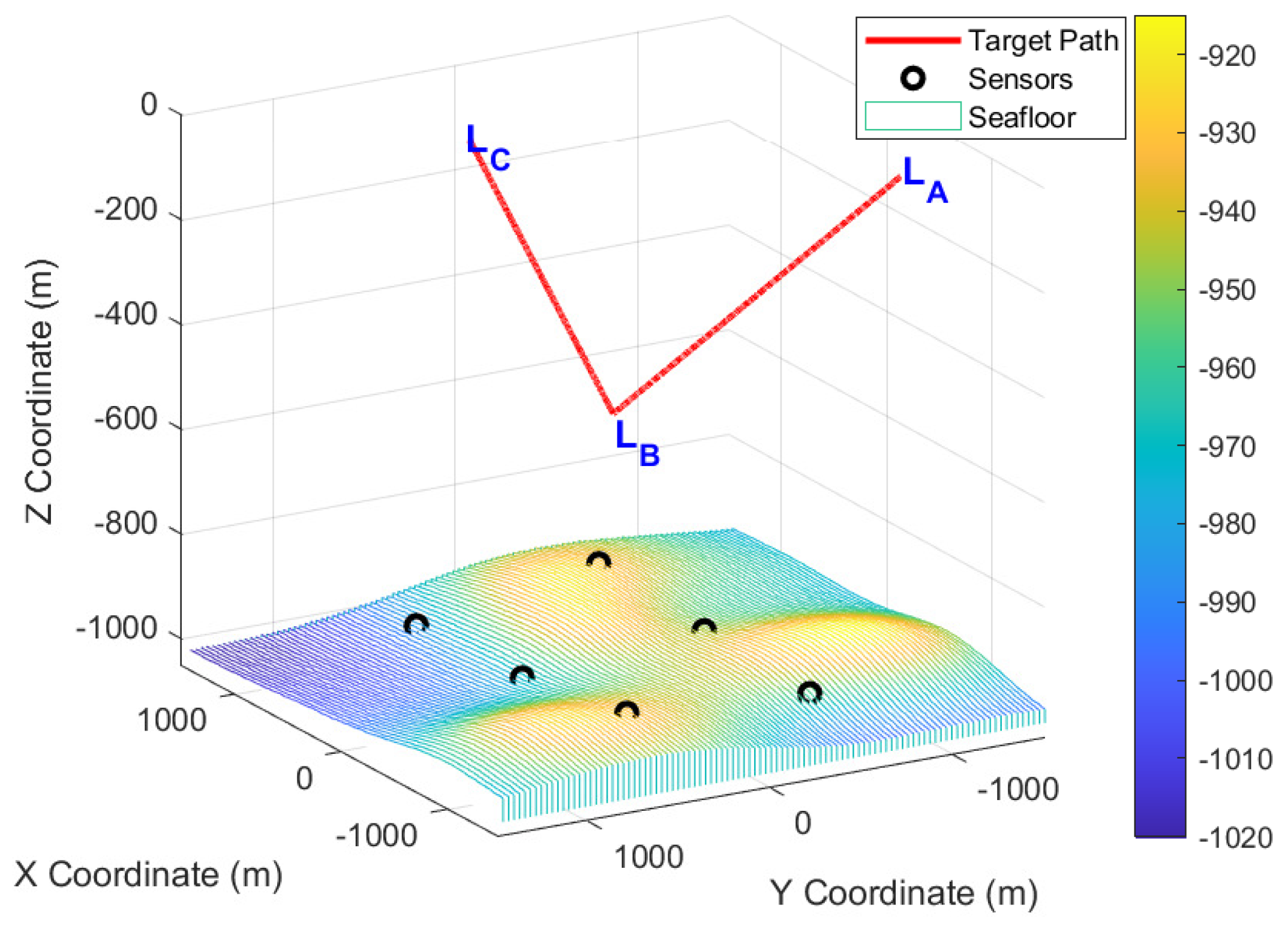
The relative relation between target motion trajectory and underwater acoustic element.
Figure 6.
The relative relation between target motion trajectory and underwater acoustic element.
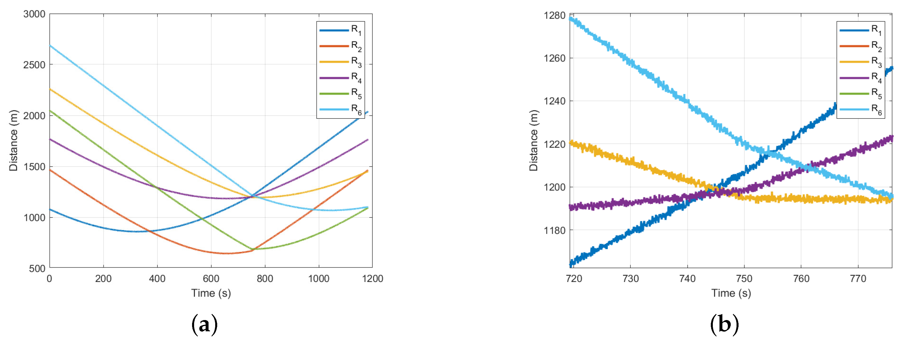
Distance infographic for LBL positioning. (a) Information graph of distance from each station to the target. (b) Local distance from each station to the target.
Figure 7.
Distance infographic for LBL positioning. (a) Information graph of distance from each station to the target. (b) Local distance from each station to the target.
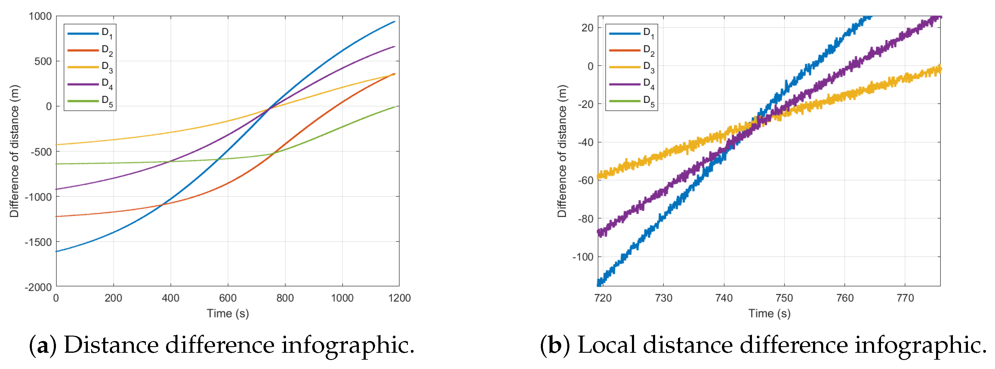
Distance difference infographic for LBL positioning.
Figure 8.
Distance difference infographic for LBL positioning.
All directions and total OC of algorithm 1.
Figure 9.
All directions and total OC of algorithm 1.
All directions and total OC of algorithm 2.
Figure 10.
All directions and total OC of algorithm 2.
All directions and total OC of algorithm 3.
Figure 11.
All directions and total OC of algorithm 3.
Comparison of the OC mean and absolute mean of three algorithms. (a) The mean OC of three algorithms. (b) The OC absolute mean of three algorithms.
Figure 12.
Comparison of the OC mean and absolute mean of three algorithms. (a) The mean OC of three algorithms. (b) The OC absolute mean of three algorithms.
Comparison of GDOP changes with UUV movement under two systems. (a) Variation of GDOP with UUV motion in range-locating system. (b) Variation of GDOP with UUV motion in range-difference positioning system.
Figure 13.
Comparison of GDOP changes with UUV movement under two systems. (a) Variation of GDOP with UUV motion in range-locating system. (b) Variation of GDOP with UUV motion in range-difference positioning system.
The relationship between GDOP and measured depth in the range-locating system. (a) Three-dimensional topographic map of GDOP (depth: 0 m). (b) Two-dimensional contours of the GDOP (depth: 0 m). (c) Three-dimensional terrain map from GDOP (depth: −400 m). (d) Two-dimensional contours of the GDOP (depth: −400 m). (e) Three-dimensional terrain map from GDOP (depth: −800 m). (f) Two-dimensional contours of the GDOP (depth: −800 m).
Figure 14.
The relationship between GDOP and measured depth in the range-locating system. (a) Three-dimensional topographic map of GDOP (depth: 0 m). (b) Two-dimensional contours of the GDOP (depth: 0 m). (c) Three-dimensional terrain map from GDOP (depth: −400 m). (d) Two-dimensional contours of the GDOP (depth: −400 m). (e) Three-dimensional terrain map from GDOP (depth: −800 m). (f) Two-dimensional contours of the GDOP (depth: −800 m).
The relationship between GDOP and measured depth in the range-difference positioning system. (a) Three-dimensional topographic map of GDOP (depth: 0 m). (b) Two-dimensional contours of the GDOP (depth: 0 m). (c) Three-dimensional terrain map from GDOP (depth: −400 m). (d) Two-dimensional contours of the GDOP (depth: −400 m). (e) Three-dimensional terrain map from GDOP (depth: −800 m). (f) Two-dimensional contours of the GDOP (depth: −800 m).
Figure 15.
The relationship between GDOP and measured depth in the range-difference positioning system. (a) Three-dimensional topographic map of GDOP (depth: 0 m). (b) Two-dimensional contours of the GDOP (depth: 0 m). (c) Three-dimensional terrain map from GDOP (depth: −400 m). (d) Two-dimensional contours of the GDOP (depth: −400 m). (e) Three-dimensional terrain map from GDOP (depth: −800 m). (f) Two-dimensional contours of the GDOP (depth: −800 m).
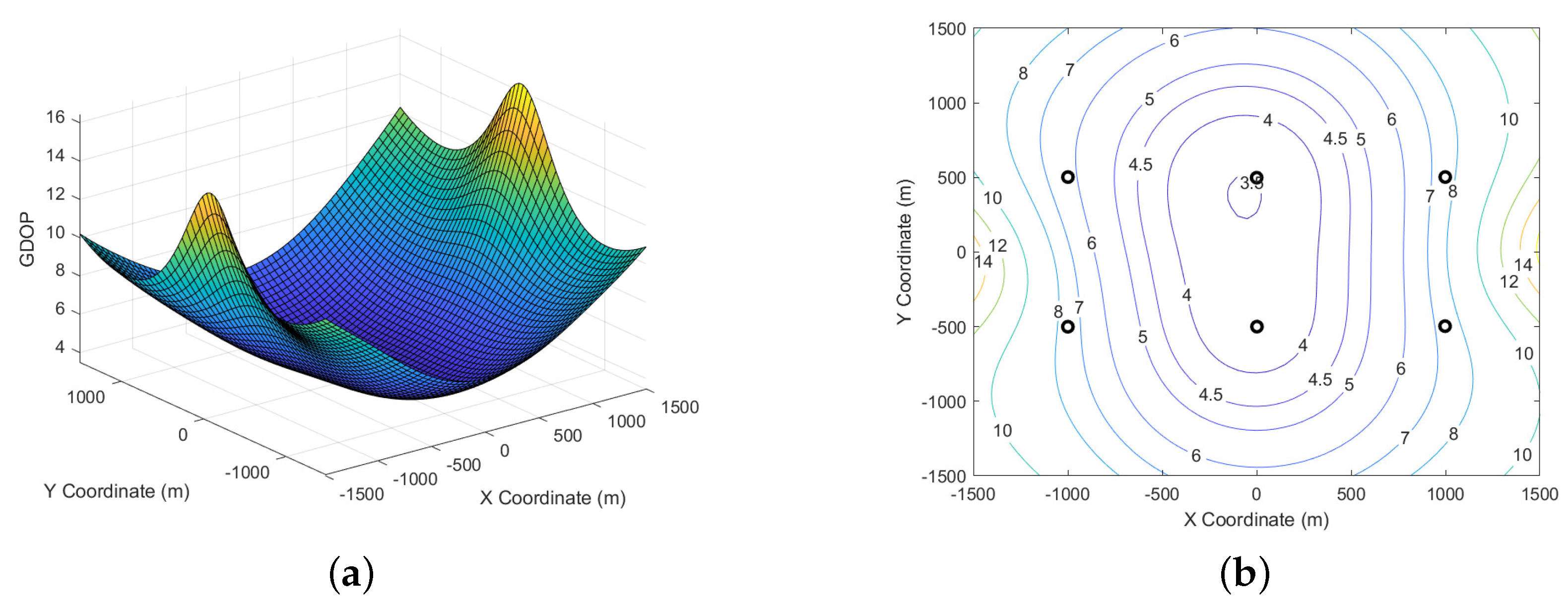
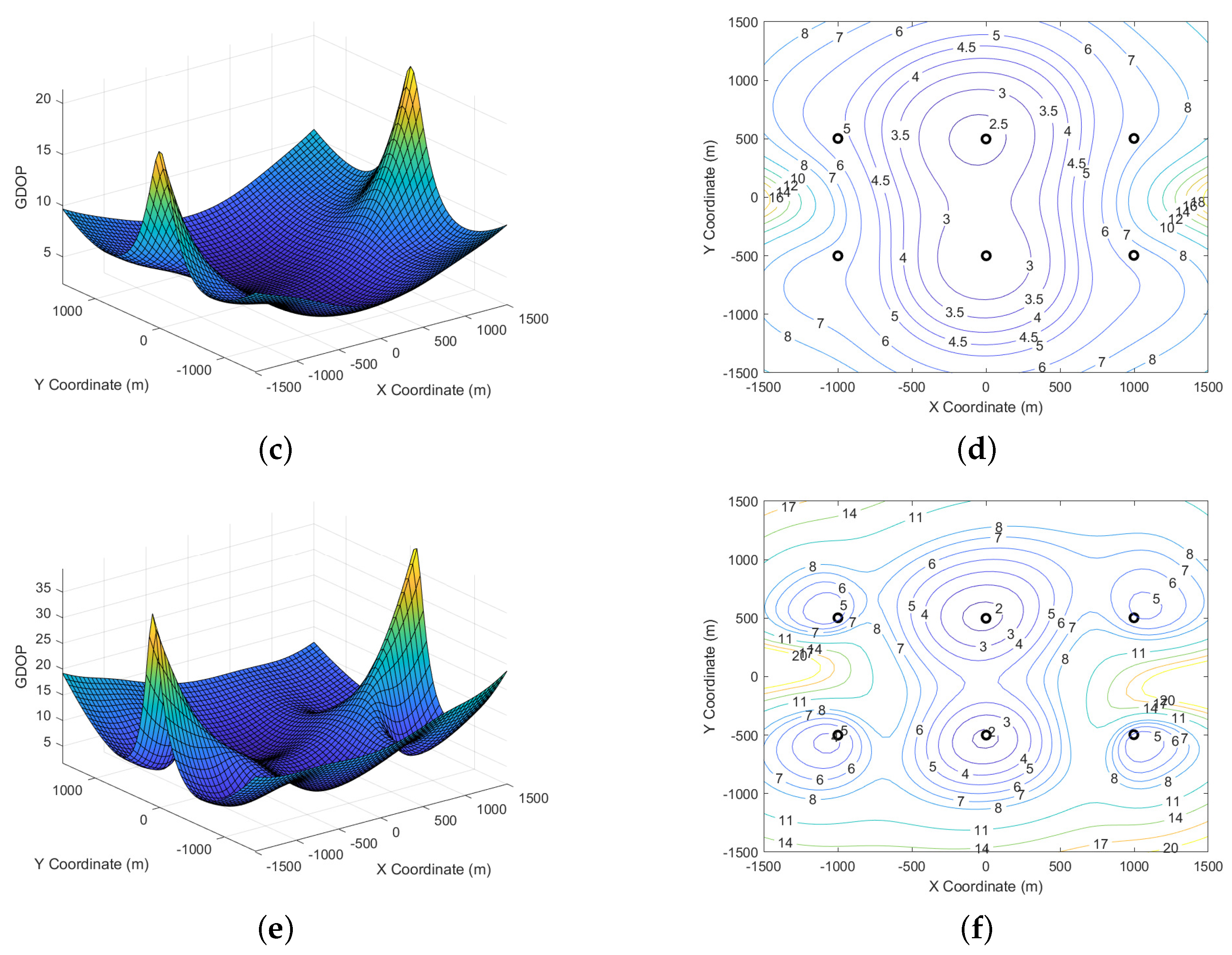
Table 1.
Dominant system error and its characteristics.
Table 1.
Dominant system error and its characteristics.
| Dominant Error | Characteristics of Equivalent Ranging Error |
|---|---|
| Constant | |
| Constant | |
| It gets bigger as it gets farther away | |
| It gets bigger as it distance becomes larger |
Table 2.
The differences and advantages of the three algorithms in error suppression ability, application scenarios, and so on (“o” means exist, “×” means do not exist).
Table 2.
The differences and advantages of the three algorithms in error suppression ability, application scenarios, and so on (“o” means exist, “×” means do not exist).
| Existing Problem | Distance Iterative Algorithm | Geometric Analytic Algorithm | Distance Difference Iterative Algorithm |
|---|---|---|---|
| Undeducted error | o | × | × |
| Bad layout geometry | × | o | × |
| Bad observational geometry | o | × | × |
Table 3.
Location coordinates of underwater acoustic elements (no calibration error).
Table 3.
Location coordinates of underwater acoustic elements (no calibration error).
| Sensor Number | X (m) | Y (m) | Z (m) |
|---|---|---|---|
| −998.5 | −499.4 | −954.9 | |
| 2.8 | −498.7 | −945.2 | |
| 998.7 | −495.4 | −927.2 | |
| −998.1 | 503.8 | −928.6 | |
| 1.3 | 499.7 | −971.7 | |
| 999.7 | 504.0 | −981.7 |
Table 4.
Comparison of all directions and total OC of the three algorithms (14991–15010 sampling points).
Table 4.
Comparison of all directions and total OC of the three algorithms (14991–15010 sampling points).
| Number | ||||||||||||
|---|---|---|---|---|---|---|---|---|---|---|---|---|
| 14991 | −0.11 | 0.08 | 2.63 | 2.64 | 0.04 | 0.30 | 2.72 | 2.73 | −0.16 | 0.02 | −0.93 | 0.95 |
| 14992 | 0.01 | 0.03 | 2.59 | 2.59 | 0.10 | 0.14 | −3.89 | 3.90 | 0.04 | 0.04 | −0.58 | 0.59 |
| 14993 | 0.13 | 0.08 | 2.61 | 2.61 | 0.25 | 0.25 | 0.96 | 1.02 | 0.09 | 0.03 | −0.65 | 0.66 |
| 14994 | 0.02 | 0.15 | 2.68 | 2.68 | 0.09 | 0.23 | −2.17 | 2.18 | 0.03 | 0.14 | 0.06 | 0.16 |
| 14995 | 0.07 | −0.01 | 2.52 | 2.53 | 0.16 | 0.04 | −1.60 | 1.61 | 0.02 | −0.06 | −0.64 | 0.64 |
| 14996 | 0.00 | 0.06 | 2.58 | 2.58 | 0.12 | 0.15 | 0.03 | 0.20 | −0.06 | 0.00 | −0.83 | 0.83 |
| 14997 | −0.02 | −0.04 | 2.75 | 2.75 | 0.14 | 0.23 | 3.20 | 3.21 | −0.04 | −0.08 | −0.53 | 0.53 |
| 14998 | −0.01 | 0.09 | 2.53 | 2.53 | 0.11 | 0.17 | 0.46 | 0.50 | −0.08 | 0.02 | -0.80 | 0.80 |
| 14999 | 0.03 | 0.04 | 2.81 | 2.81 | 0.12 | 0.05 | −2.12 | 2.12 | −0.02 | −0.01 | −0.35 | 0.35 |
| 15000 | −0.08 | −0.04 | 2.64 | 2.64 | 0.03 | 0.09 | 2.02 | 2.02 | −0.13 | −0.09 | −0.11 | 0.19 |
| 15001 | 0.01 | 0.01 | 2.53 | 2.53 | 0.15 | 0.14 | −0.79 | 0.82 | −0.03 | −0.05 | −1.23 | 1.24 |
| 15002 | 0.03 | 0.02 | 2.59 | 2.59 | 0.13 | 0.08 | −2.32 | 2.32 | 0.00 | −0.02 | −0.81 | 0.81 |
| 15003 | 0.01 | −0.06 | 2.61 | 2.61 | 0.13 | 0.10 | −0.79 | 0.80 | 0.02 | −0.07 | −0.45 | 0.46 |
| 15004 | −0.05 | −0.07 | 2.69 | 2.69 | 0.10 | 0.14 | 3.49 | 3.50 | −0.12 | −0.15 | −0.73 | 0.76 |
| 15005 | 0.04 | 0.12 | 2.66 | 2.66 | 0.14 | 0.15 | −1.39 | 1.41 | −0.01 | 0.05 | -0.58 | 0.59 |
| 15006 | 0.04 | −0.05 | 2.53 | 2.53 | 0.18 | 0.08 | 0.82 | 0.84 | −0.02 | −0.13 | −1.11 | 1.12 |
| 15007 | 0.14 | 0.29 | 2.67 | 2.69 | 0.28 | 0.47 | −0.81 | 0.97 | 0.14 | 0.26 | −0.87 | 0.92 |
| 15008 | 0.10 | 0.12 | 2.58 | 2.58 | 0.22 | 0.33 | 0.65 | 0.76 | 0.11 | 0.11 | −0.24 | 0.29 |
| 15009 | 0.08 | 0.01 | 2.67 | 2.67 | 0.23 | 0.21 | 1.93 | 1.95 | 0.02 | −0.06 | −1.07 | 1.07 |
| 15010 | 0.05 | 0.11 | 2.66 | 2.66 | 0.20 | 0.39 | 3.46 | 3.48 | 0.03 | 0.08 | −0.38 | 0.39 |
Disclaimer/Publisher’s Note: The statements, opinions and data contained in all publications are solely those of the individual author(s) and contributor(s) and not of MDPI and/or the editor(s). MDPI and/or the editor(s) disclaim responsibility for any injury to people or property resulting from any ideas, methods, instructions or products referred to in the content. |
Source link
Huiyu Chen www.mdpi.com

