
1. Introduction
Despite these advances, constructing localized scalable DNA logic circuit systems remains a challenge. Here, we first constructed elementary two-input AND and OR logic circuits on a DNA origami surface, where logic operations were realized by triggering the SDR. We then showed that the constructed elementary logic circuits can be scaled up to form localized DNA logic circuit systems that perform arbitrary digital computing tasks, including square root functions, full adder and full subtractor. Lastly, we programmed and designed the elementary logic circuits and realized the application of the localized DNA logic circuit systems in three-satisfiability (3-SAT) problem solving and disease classification. In this work, we employed Visual DSD software (version “v2015-0325”) to simulate all the constructed DNA logic circuit systems, and the results showed that all the systems exhibit good stability and feasibility.
2. Results
2.1. Construction and Implementation of Elementary Logic Circuits and Cascades on the DNA Origami Surface
2.2. Scaling up the Localized DNA Logic Circuit Systems for Digital Computing
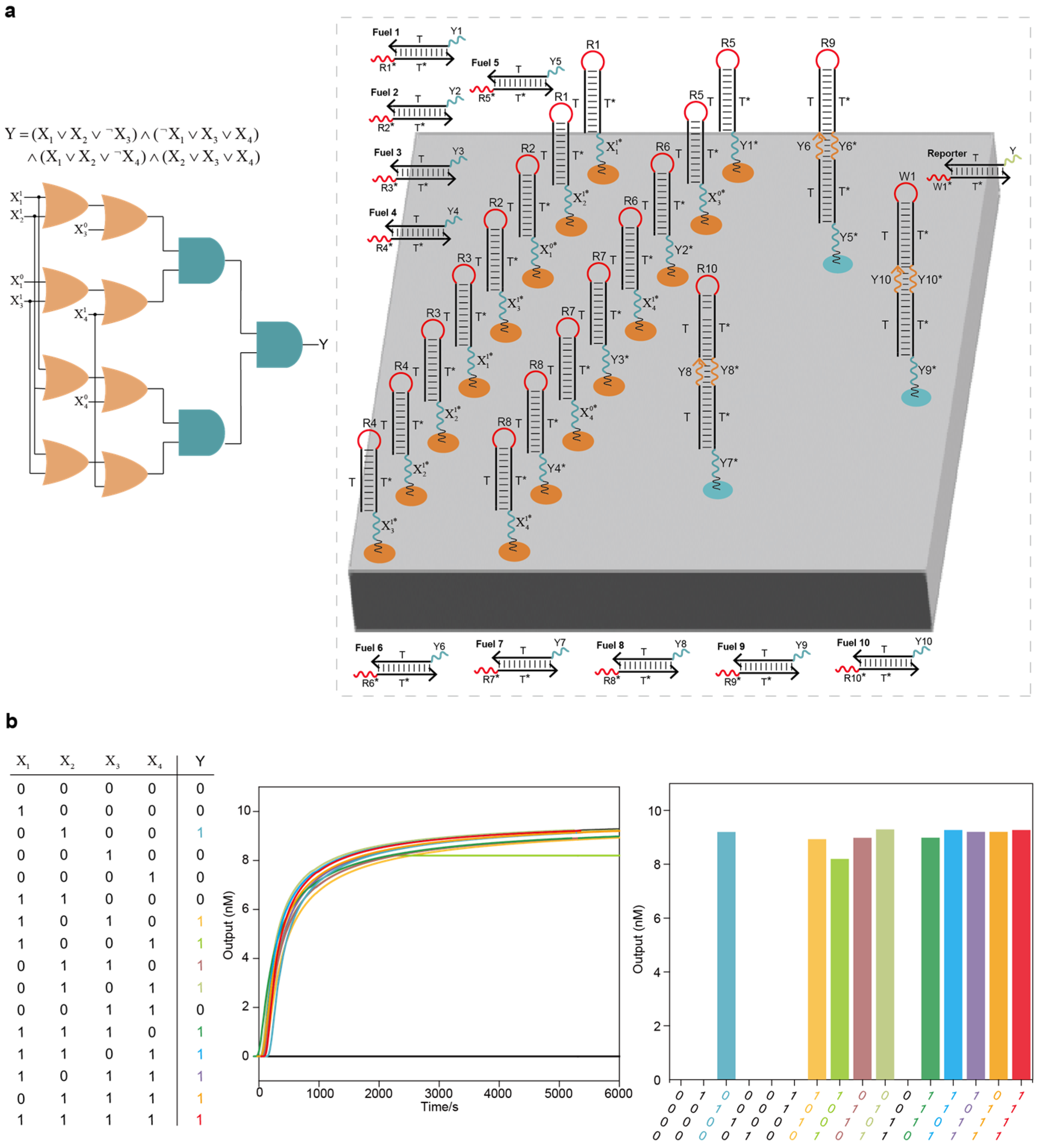
2.3. Integrated Localized DNA Logic Circuit Systems for Solving the 3-SAT Problem
2.4. Localized DNA Logic Circuit Systems for Disease Classification
3. Discussion
Herein, we demonstrated a strategy for constructing localized scalable DNA logic circuit systems based on the DNA origami surface. We first constructed elementary two-input AND and OR logic circuits on the DNA origami surface using only one and two circuit components, respectively. We then showed that the constructed elementary logic circuits can be scaled up to an arbitrary localized circuit system to implement functions such as square root circuit, full adder and full subtractor. The constructed localized scalable DNA logic circuit system based on the DNA origami surface has several advantages as follows: (1) The first is scalability, whereby the elementary two-input AND and OR logic circuits can be scaled up into large-scale localized DNA logic circuit systems. In addition, compared with the threshold strategy, our strategy involved the use of fewer circuit components on the DNA origami surface, which effectively avoids signal attenuation caused by having many components. (2) The second is modularity, which allows circuit components to be embedded anywhere in the system, and different logic functions are realized through reasonable cascading design. (3) The third is strong functionality; the constructed localized DNA logic circuit system can be effectively applied to digital computing and disease diagnosis (such as solving 3-SAT problems and classification of disease states).
We believe that the programmability and scalability of the constructed localized DNA logic circuit systems can be extended in the fields of digital computation, disease diagnosis and NP-complete problem solving. However, there are challenges that need to be addressed as the size of the problem or the amount of data associated with the disease increases. Such challenges include the following: (1) Further scaling of the size of the localized DNA logic circuit systems is constrained by the size of the DNA origami, and DNA origami of a larger size is required. (2) When performing disease diagnosis, the logic circuit system can only passively receive the 0/1 signal (for example, the miRNA expression level is set to 1 above the threshold concentration and 0 below the threshold concentration) and realize a classification decision, and logic circuit system cannot directly read the miRNA expression level above/below the threshold concentration from the samples, which impacts the efficiency and integration of disease diagnosis. Introducing a DNA chemical reaction network that can directly read the expression level of miRNA represents a potential future direction.
4. Materials and Methods
4.1. Simulation Experiments Based on Visual DSD Software
4.2. Silicon-Based Training of Germ Cell Tumor (GCT) Data
or by the mean of the regression tree:
The experimental environment was Windows 10 operating system and Intel Core i5. We screened out the characteristic miRNAs (miRNA-345, miRNA-17, miRNA-139, miRNA-210, miRNA-7705 and miRNA-1-1) associated with GCT, achieving 94% accuracy in GCT identification.
5. Conclusions
DNA origami provides a nanoscale addressable surface for the construction of DNA logic circuit systems. These localized DNA logic circuit systems constrained on the DNA origami surface have faster reaction dynamics than discrete DNA logic circuit systems. Therefore, in this paper, we proposed a strategy for constructing localized scalable DNA logic circuit systems based on a DNA origami surface and further implemented complex logic circuit systems such as square root circuit, full adder, full subtractor and logic circuit systems for solving 3-SAT problems and disease classification. This strategy involved the use of fewer circuit components on the DNA origami surface to achieve the construction of DNA logic circuit systems. We verified the feasibility, scalability and stability of the constructed localized DNA logic circuit systems through simulation experiments based on Visual DSD software. This work is expected to provide a solid foundation for intelligent integrated DNA computing systems.
Supplementary Materials
Author Contributions
Conceptualization, Z.T. and Z.Y.; methodology, Z.T.; software, Z.T., S.L. and C.C.; validation, Z.T., Z.Z. and Z.Y.; formal analysis, S.L.; investigation, Z.T.; resources, Z.Y.; data curation, Z.Y.; writing—original draft preparation, Z.T.; writing—review and editing, Z.Y.; visualization, S.L., C.C. and Z.Z.; supervision, Z.T.; project administration, Z.Y.; funding acquisition, Z.T. and Z.Y. All authors have read and agreed to the published version of the manuscript.
Funding
This research was funded by the National Natural Science Foundation of China (grant numbers: 22307072 and 62272005) and sponsored by the Chenguang Program supported by the Shanghai Education Development Foundation and Shanghai Municipal Education Commission.
Institutional Review Board Statement
Not applicable.
Informed Consent Statement
Not applicable.
Data Availability Statement
Conflicts of Interest
The authors declare no conflicts of interest.
Abbreviations
| SDR | Strand Displacement Reaction |
| 3-SAT | Three-Satisfiability |
| miRNA | MicroRNA |
| GCT | Germ Cell Tumor |
| TCGA | The Cancer Genome Atlas |
| NP | Non-deterministic Polynomial |
| DNA | Deoxyribonucleic Acid |
| nt | nucleotide |
References
- Seelig, G.; Soloveichik, D.; Zhang, D.Y.; Winfree, E. Enzyme-free nucleic acid logic circuits. Science 2006, 314, 1585–1588. [Google Scholar] [CrossRef] [PubMed]
- Qian, L.L.; Winfree, E. Scaling up digital circuit computation with DNA strand displacement cascades. Science 2011, 332, 1196–1201. [Google Scholar] [CrossRef] [PubMed]
- Lv, H.; Xie, N.L.; Li, M.Q.; Dong, M.K.; Sun, C.Y.; Zhang, Q.; Zhao, L.; Li, J.; Zuo, X.L.; Chen, H.B.; et al. DNA-based programmable gate arrays for general-purpose DNA computing. Nature 2023, 622, 292–300. [Google Scholar] [CrossRef]
- Adleman, L.M. Molecular computation of solutions to combinatorial problems. Science 1994, 266, 1021–1024. [Google Scholar] [CrossRef] [PubMed]
- Santini, C.C.; Bath, J.; Turberfield, A.J.; Tyrrell, A.M. A DNA network as an information processing system. Int. J. Mol. Sci. 2012, 13, 5125–5137. [Google Scholar] [CrossRef] [PubMed]
- Cherry, K.M.; Qian, L.L. Scaling up molecular pattern recognition with DNA-based winner-take-all neural networks. Nature 2018, 559, 370–376. [Google Scholar] [CrossRef]
- Wang, J.; Zhang, X.K.; Shi, P.J.; Cao, B.; Wang, B. A DNA finite-state machine based on the programmable allosteric strategy of DNAzyme. Int. J. Mol. Sci. 2023, 24, 3588. [Google Scholar] [CrossRef]
- Xiong, X.W.; Zhu, T.; Zhu, Y.; Cao, M.Y.; Xiao, J.; Li, L.; Wang, F.; Fan, C.H.; Pei, H. Molecular convolutional neural networks with DNA regulatory circuits. Nat. Mach. Intell. 2022, 4, 625–635. [Google Scholar] [CrossRef]
- Wang, Z.C.; Pu, J.; Cao, L.L.; Tian, J. A parallel biological optimization algorithm to solve the unbalanced assignment problem based on DNA molecular computing. Int. J. Mol. Sci. 2015, 16, 25338–25352. [Google Scholar] [CrossRef] [PubMed]
- Zhang, C.; Zheng, T.T.; Ma, Q.; Yang, L.L.; Zhang, M.Z.; Wang, J.Y.; Teng, X.Y.; Miao, Y.Y.; Lin, H.C.; Yang, Y.; et al. Logical analysis of multiple single-nucleotide-polymorphisms with programmable DNA molecular computation for clinical diagnostics. Angew Chem. Int. Ed. Engl. 2022, 4, e202117658. [Google Scholar] [CrossRef] [PubMed]
- Yin, F.F.; Zhao, H.P.; Lu, S.S.; Shen, J.W.; Li, M.; Mao, X.H.; Li, F.; Shi, J.Y.; Li, J.; Dong, B.J.; et al. DNA-framework-based multidimensional molecular classifiers for cancer diagnosis. Nat. Nanotechnol. 2023, 18, 677–686. [Google Scholar] [CrossRef]
- Yin, J.; Wang, S.Y.; Wang, J.H.; Zhang, Y.W.; Fan, C.H.; Chao, J.; Gao, Y.; Wang, L.H. An intelligent DNA nanodevice for precision thrombolysis. Nat. Mater. 2024, 23, 854–862. [Google Scholar] [CrossRef] [PubMed]
- Benenson, Y.; Paz-Elizur, T.; Adar, R.; Keinan, E.; Livneh, Z.; Shapiro, E. Programmable and autonomous computing machine made of biomolecules. Nature 2001, 414, 430–434. [Google Scholar] [CrossRef] [PubMed]
- Wang, F.; Lv, H.; Li, Q.; Li, J.; Zhang, X.L.; Shi, J.Y.; Wang, L.H.; Fan, C.H. Implementing digital computing with DNA-based switching circuits. Nat. Commun. 2020, 11, 121. [Google Scholar] [CrossRef]
- Liu, C.J.; Liu, Y.; Zhu, E.Q.; Zhang, Q.; Wei, X.P.; Wang, B. Cross-Inhibitor: A time-sensitive molecular circuit based on DNA strand displacement. Nucleic Acids Res. 2020, 48, 10691–10701. [Google Scholar] [CrossRef] [PubMed]
- Lapteva, A.P.; Sarraf, N.; Qian, L.L. DNA strand-displacement temporal logic circuits. J. Am. Chem. Soc. 2022, 144, 12443–12449. [Google Scholar] [CrossRef] [PubMed]
- Xie, N.L.; Li, M.Q.; Wang, Y.; Lv, H.; Shi, J.Y.; Li, J.; Li, Q.; Wang, F.; Fan, C.H. Scaling up multi-bit DNA full adder circuits with minimal strand displacement reactions. J. Am. Chem. Soc. 2022, 144, 9479–9488. [Google Scholar] [CrossRef] [PubMed]
- Bucci, J.; Irmisch, P.; Grosso, E.D.; Seidel, R.; Ricci, F. Timed pulses in DNA strand displacement reactions. J. Am. Chem. Soc. 2023, 145, 20968–20974. [Google Scholar] [CrossRef] [PubMed]
- Teichmann, M.; Kopperger, E.; Simmel, F.C. Robustness of localized DNA strand displacement cascades. ACS Nano 2014, 8, 8487–8496. [Google Scholar] [CrossRef]
- Dalchau, N.; Chandran, H.; Gopalkrishnan, N.; Phillips, A.; Reif, J. Probabilistic analysis of localized DNA hybridization circuits. ACS Synth. Biol. 2015, 4, 898–913. [Google Scholar] [CrossRef]
- Ruiz, I.M.; Arbona, J.M.; Lad, A.; Mendoza; Aiméa, J.P.; Elezgaray, J. Connecting localized DNA strand displacement reactions. Nanoscale 2015, 7, 12970–12978. [Google Scholar] [CrossRef]
- Seeman, N.C. Nucleic acid junctions and lattices. J. Theor. Biol. 1982, 99, 37–47. [Google Scholar] [CrossRef]
- Bui, H.; Shah, S.; Mokhtar, R.; Song, T.Q.; Garg, S.; Reif, J. Localized DNA hybridization chain reactions on DNA origami. ACS Nano 2018, 12, 1146–1155. [Google Scholar] [CrossRef]
- Petersen, P.; Tikhomirov, G.; Qian, L.L. Information-based autonomous reconfiguration in systems of interacting DNA nanostructures. Nat. Commun. 2018, 9, 5362. [Google Scholar] [CrossRef]
- Liu, L.; Hong, F.; Liu, H.; Zhou, X.; Jiang, S.X.; Sulc, P.; Jiang, J.H.; Yan, H. A localized DNA finite-state machine with temporal resolution. Sci. Adv. 2022, 8, eabm9530. [Google Scholar] [CrossRef] [PubMed]
- Sarraf, N.; Rodriguez, K.R.; Qian, L.L. Modular reconfiguration of DNA origami assemblies using tile displacement. Sci. Robot. 2023, 8, eadf1511. [Google Scholar] [CrossRef] [PubMed]
- Tikhomirov, G.; Petersen, P.; Qian, L.L. Fractal assembly of micrometre-scale DNA origami arrays with arbitrary patterns. Nature 2017, 552, 67–71. [Google Scholar] [CrossRef] [PubMed]
- Thubagere, A.J.; Li, W.; Johnson, R.F.; Chen, Z.; Doroudi, S.; Lee, Y.; Izatt, G.; Wittman, S.; Srinivas, N.; Woods, D.; et al. A cargo-sorting DNA robot. Science 2017, 357, eaan6558. [Google Scholar] [CrossRef] [PubMed]
- Chatterjee, G.; Dalchau, N.; Muscat, R.A.; Phillips, A.; Seelig, G. A spatially localized architecture for fast and modular DNA computing. Nat. Nanotechnol. 2017, 12, 920–927. [Google Scholar] [CrossRef] [PubMed]
- Chao, J.; Wang, J.; Wang, F.; Ouyang, X.Y.; Kopperger, E.; Liu, H.J.; Li, Q.; Shi, J.Y.; Wang, L.H.; Hu, J.; et al. Solving mazes with single-molecule DNA navigators. Nat. Mater. 2019, 18, 273–279. [Google Scholar] [CrossRef] [PubMed]
- Yang, L.L.; Tang, Q.; Zhang, M.Z.; Tian, Y.; Chen, X.X.; Xu, R.; Ma, Q.; Guo, P.; Zhang, C.; Han, D. A spatially localized DNA linear classifier for cancer diagnosis. Nat. Commun. 2024, 15, 4583. [Google Scholar] [CrossRef] [PubMed]
- Zhang, Q.; Li, M.Q.; Tang, Y.Q.; Zhang, J.Y.; Sun, C.Y.; Hao, Y.Y.; Cheng, J.N.; Xie, X.D.; Jia, S.S.; Lv, H.; et al. High-speed sequential DNA computing using a solid-state DNA origami register. ACS Cent. Sci. 2024, 10, 2285–2293. [Google Scholar] [CrossRef] [PubMed]
- Phillips, A.; Cardelli, L. A programming language for composable DNA circuits. J. R. Soc. Interface 2009, 6, S419–S436. [Google Scholar] [CrossRef]
- Lakin, M.R.; Youssef, S.; Polo, F.; Emmott, S.; Phillips, A. Visual DSD: A design and analysis tool for DNA strand displacement systems. Bioinformatics 2011, 27, 3211–3213. [Google Scholar] [CrossRef] [PubMed]
- Lakin, M.R.; Paulevé, L.; Phillips, A. Stochastic simulation of multiple process calculi for biology. Theor. Comput. Sci. 2012, 431, 181–206. [Google Scholar] [CrossRef]
- Chen, Y.; Dalchau, N.; Srinivas, N.; Phillips, A.; Cardelli, L.; Soloveichik, D.; Seelig, G. Programmable chemical controllers made from DNA. Nat. Nanotechnol. 2013, 8, 755–762. [Google Scholar] [CrossRef]
- Yordanov, B.; Kim, J.; Petersen, R.L.; Shudy, A.; Kulkarni, V.V.; Phillips, A. Computational design of nucleic acid feedback control circuits. ACS Synth. Biol. 2014, 3, 600–616. [Google Scholar] [CrossRef]
- Spaccasassi, C.; Lakin, M.R.; Phillips, A. A logic programming language for computational nucleic acid devices. ACS Synth. Biol. 2019, 8, 1530–1547. [Google Scholar] [CrossRef] [PubMed]
- Lakin, M.R.; Youssef, S.; Cardelli, L.; Phillips, A. Abstractions for DNA circuit design. J. R. Soc. Interface 2012, 9, 470–486. [Google Scholar] [CrossRef]
- Jungmann, R.; Avendaño, M.S.; Dai, M.; Woehrstein, J.B.; Agasti, S.S.; Feiger, Z.; Rodal, A.; Yin, P. Quantitative super-resolution imaging with qPAINT. Nat. Methods 2016, 13, 439–442. [Google Scholar] [CrossRef] [PubMed]
- Strauss, M.T.; Schueder, F.; Haas, D.; Nickels, C.P.; Jungmann, R. Quantifying absolute addressability in DNA origami with molecular resolution. Nat. Commun. 2018, 9, 1600. [Google Scholar] [CrossRef] [PubMed]
- Lipton, R.J. DNA solution of hard computational problems. Science 1995, 268, 542–545. [Google Scholar] [CrossRef]
- Braich, R.S.; Chelyapov, N.; Johnson, C.; Rothemund, P.W.K.; Adleman, L. Solution of a 20-variable 3-SAT problem on a DNA computer. Science 2002, 296, 499–502. [Google Scholar] [CrossRef] [PubMed]
- Rothemund, P.W.K. Folding DNA to create nanoscale shapes and patterns. Nature 2006, 440, 297–302. [Google Scholar] [CrossRef] [PubMed]
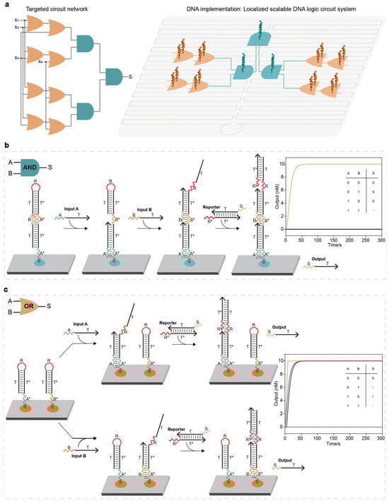
Construction of the localized elementary DNA logic circuit: (a) An abstraction of a localized DNA logic circuit system. Scaling up elementary logic circuits into localized DNA logic circuit systems through deliberate programming allows for the realization of a targeted circuit network. (b) Elementary two-input AND logic circuit. The entire system consisted of a localized DNA complex (with two toeholds A* and B*) and a reporter molecule. The base sequences of domain and domain* of the same letter were completely complementary. When two signal strands were added, the hairpin of the DNA complex was opened and reacted with the reporter molecule, displacing the output strand and producing a high signal. (c) Elementary two-input OR logic circuit. The entire system consisted of two localized hairpin DNA strands with two toeholds (A* and B*) and a reporter molecule. Once an input strand was added, the hairpin of the DNA strand was opened and reacted with the reporter molecule, displacing the output strand and producing a high signal. The colorful lines corresponded to reaction kinetics curves with the same color numbers.
Figure 1.
Construction of the localized elementary DNA logic circuit: (a) An abstraction of a localized DNA logic circuit system. Scaling up elementary logic circuits into localized DNA logic circuit systems through deliberate programming allows for the realization of a targeted circuit network. (b) Elementary two-input AND logic circuit. The entire system consisted of a localized DNA complex (with two toeholds A* and B*) and a reporter molecule. The base sequences of domain and domain* of the same letter were completely complementary. When two signal strands were added, the hairpin of the DNA complex was opened and reacted with the reporter molecule, displacing the output strand and producing a high signal. (c) Elementary two-input OR logic circuit. The entire system consisted of two localized hairpin DNA strands with two toeholds (A* and B*) and a reporter molecule. Once an input strand was added, the hairpin of the DNA strand was opened and reacted with the reporter molecule, displacing the output strand and producing a high signal. The colorful lines corresponded to reaction kinetics curves with the same color numbers.
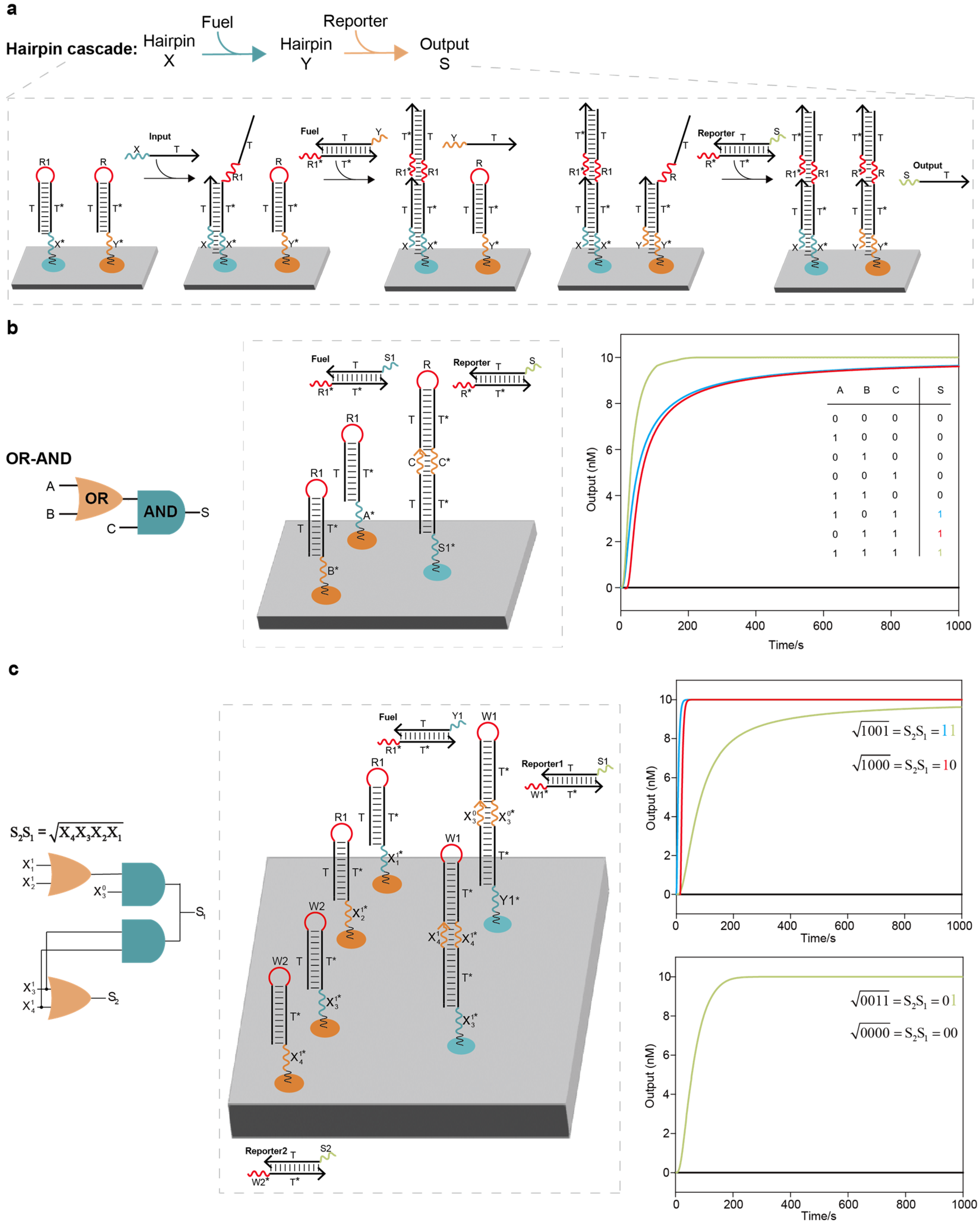
Implementation of the localized elementary DNA logic circuit cascade and localized DNA logic circuit system for computing the floor of the square root of a four-bit binary number: (a) Hairpin cascade. The two hairpin DNA strands were cascaded with the assistance of the fuel strand. (b) OR–AND circuit cascade. The entire system consisted of 1 elementary OR circuit, 1 AND circuit, 1 fuel strand and 1 reporter molecule. For the localized OR–AND logic circuit system based on the threshold strategy, it was necessary to anchor roughly 6 circuit components on the DNA origami surface; in our work, however, it was only necessary to anchor 3 circuit components, reducing the required number of strands by nearly 50%. (c) Localized DNA logic circuit system for computing the floor of the square root of a four-bit binary number. The entire circuit system had two layers, including the cascade of 2 OR circuits and 2 AND circuits, 1 fuel strand and 2 reporter molecules. For the circuit system based on the threshold strategy to compute the floor of the square root of a four-bit binary number, it was necessary to anchor roughly 12 circuit components on the DNA origami surface; in our work, however, it was only necessary to anchor 6 components, reducing the required number of strands by nearly 50%. Four representative examples are shown in the right column.
Figure 2.
Implementation of the localized elementary DNA logic circuit cascade and localized DNA logic circuit system for computing the floor of the square root of a four-bit binary number: (a) Hairpin cascade. The two hairpin DNA strands were cascaded with the assistance of the fuel strand. (b) OR–AND circuit cascade. The entire system consisted of 1 elementary OR circuit, 1 AND circuit, 1 fuel strand and 1 reporter molecule. For the localized OR–AND logic circuit system based on the threshold strategy, it was necessary to anchor roughly 6 circuit components on the DNA origami surface; in our work, however, it was only necessary to anchor 3 circuit components, reducing the required number of strands by nearly 50%. (c) Localized DNA logic circuit system for computing the floor of the square root of a four-bit binary number. The entire circuit system had two layers, including the cascade of 2 OR circuits and 2 AND circuits, 1 fuel strand and 2 reporter molecules. For the circuit system based on the threshold strategy to compute the floor of the square root of a four-bit binary number, it was necessary to anchor roughly 12 circuit components on the DNA origami surface; in our work, however, it was only necessary to anchor 6 components, reducing the required number of strands by nearly 50%. Four representative examples are shown in the right column.
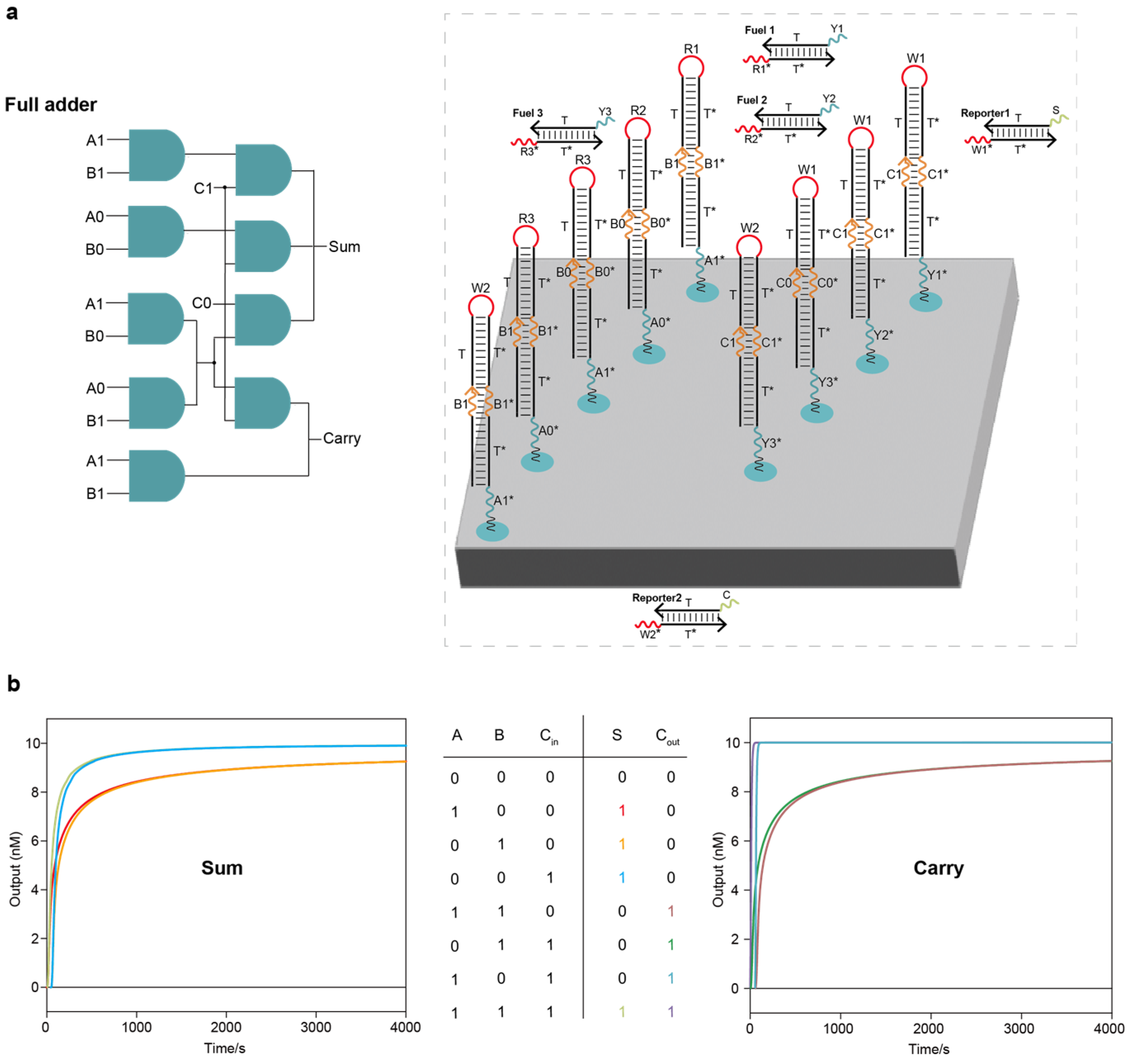
Localized DNA full adder circuit system: (a) The layout of the DNA full adder circuit system on the DNA origami surface. The entire full adder circuit system had two layers, including 9 AND circuits, 3 fuel strands and 2 reporter molecules. (b) Test results under all input combinations using Visual DSD software.
Figure 3.
Localized DNA full adder circuit system: (a) The layout of the DNA full adder circuit system on the DNA origami surface. The entire full adder circuit system had two layers, including 9 AND circuits, 3 fuel strands and 2 reporter molecules. (b) Test results under all input combinations using Visual DSD software.
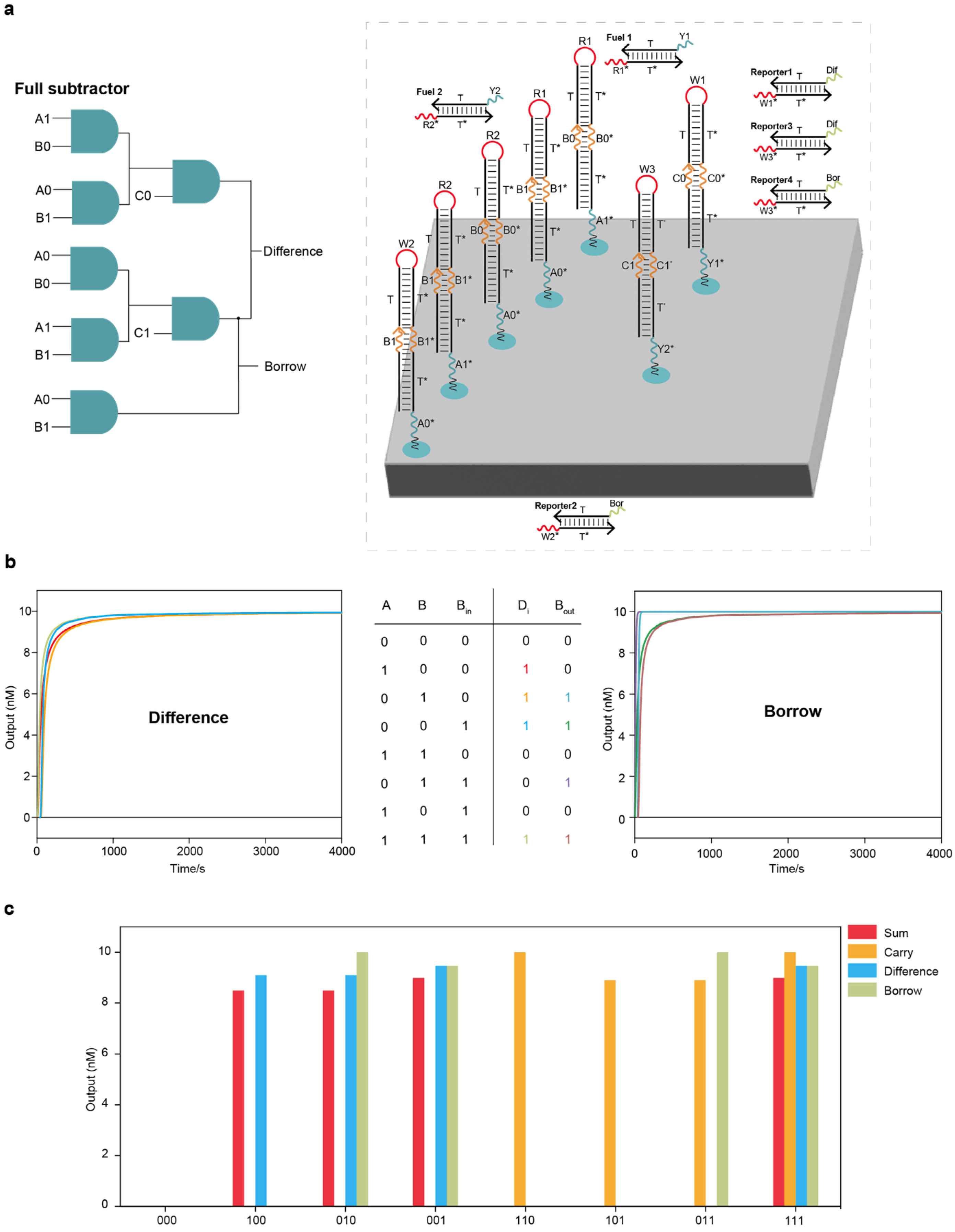
Localized DNA full subtractor circuit system and parallel computing of full adder and full subtractor circuit systems: (a) The layout of the DNA full subtractor circuit system on the DNA origami surface. The entire full subtractor circuit system had two layers, including 7 AND circuits, 2 fuel strands and 4 reporter molecules. (b) Test results under all input combinations using Visual DSD software. (c) Test results of parallel computing of full adder and full subtractor circuit systems using Visual DSD software.
Figure 4.
Localized DNA full subtractor circuit system and parallel computing of full adder and full subtractor circuit systems: (a) The layout of the DNA full subtractor circuit system on the DNA origami surface. The entire full subtractor circuit system had two layers, including 7 AND circuits, 2 fuel strands and 4 reporter molecules. (b) Test results under all input combinations using Visual DSD software. (c) Test results of parallel computing of full adder and full subtractor circuit systems using Visual DSD software.
Integrated DNA logic circuit system for solving the 3-SAT problem: (a) The 3-SAT problem with 4 variables and the layout of the integrated DNA logic circuit system on the DNA origami surface. The entire system had 4 layers, including 8 OR circuits, 3 AND circuits, 10 fuel strands and 1 reporter molecule. (b) Test results under all input combinations using Visual DSD software. There were 10 solutions to this 3-SAT problem in the data pool of 16 possible solutions.
Figure 5.
Integrated DNA logic circuit system for solving the 3-SAT problem: (a) The 3-SAT problem with 4 variables and the layout of the integrated DNA logic circuit system on the DNA origami surface. The entire system had 4 layers, including 8 OR circuits, 3 AND circuits, 10 fuel strands and 1 reporter molecule. (b) Test results under all input combinations using Visual DSD software. There were 10 solutions to this 3-SAT problem in the data pool of 16 possible solutions.
Localized DNA logic circuit systems for disease classification: (a) A decision tree model for GCT classification based on miRNA expression data of GCT samples from TCGA and the random forest algorithm. (b) The decision tree model mapping into the logic circuit system. (c) The layout of the localized DNA logic circuit system for GCT classification. (d) Confusion matrix analysis of the 87 samples. (e) Testing of the GCT classification for all 25 randomized samples showed agreement between the actual disease states labeled in TCGA, the random forest model and the constructed localized DNA logic circuit system.
Figure 6.
Localized DNA logic circuit systems for disease classification: (a) A decision tree model for GCT classification based on miRNA expression data of GCT samples from TCGA and the random forest algorithm. (b) The decision tree model mapping into the logic circuit system. (c) The layout of the localized DNA logic circuit system for GCT classification. (d) Confusion matrix analysis of the 87 samples. (e) Testing of the GCT classification for all 25 randomized samples showed agreement between the actual disease states labeled in TCGA, the random forest model and the constructed localized DNA logic circuit system.
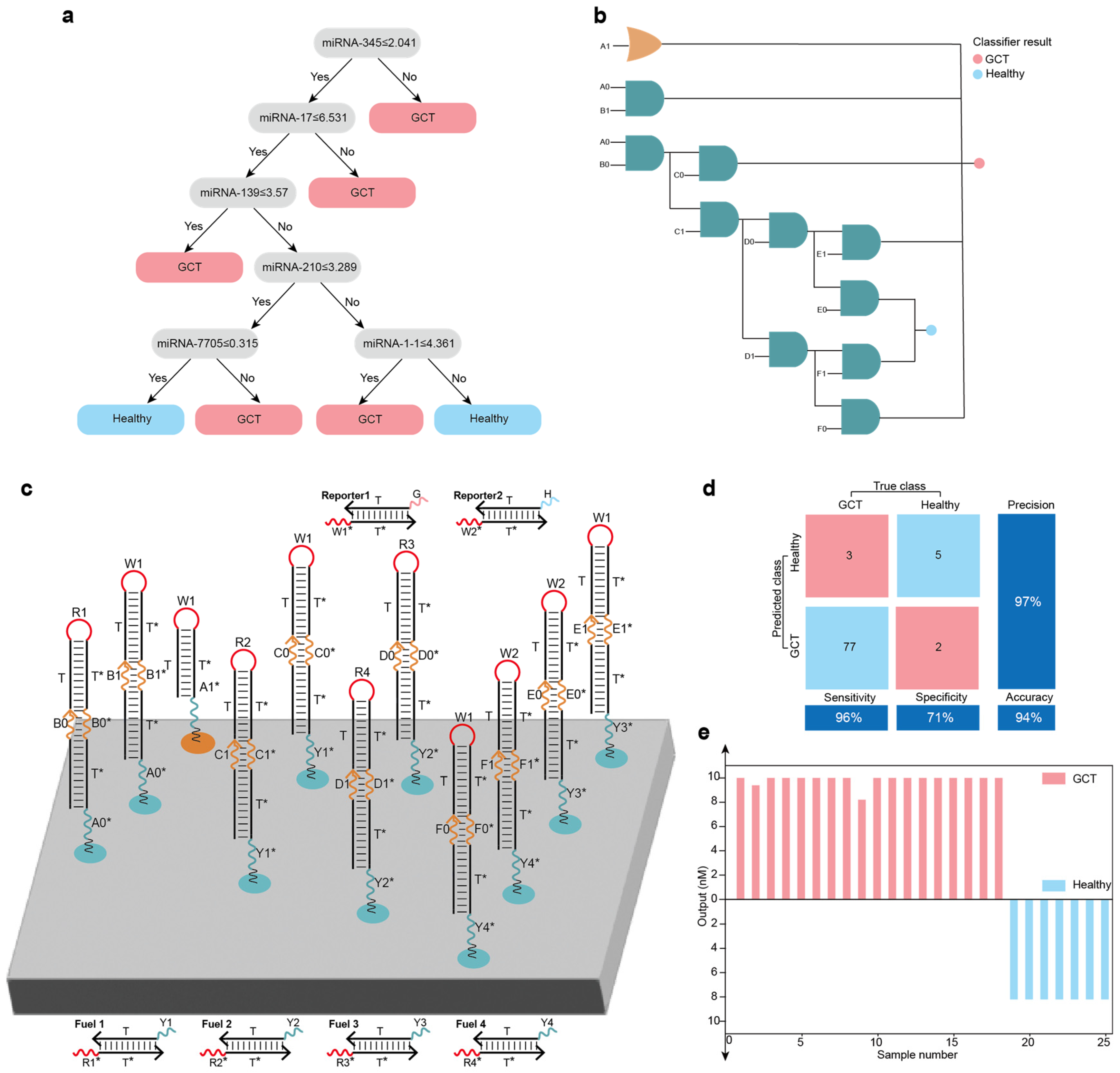
Table 1.
The main parameters of the Visual DSD simulation programs.
Table 1.
The main parameters of the Visual DSD simulation programs.
| Species | Parameters |
|---|---|
| The lengths of all toeholds | 6 nt |
| The lengths of all recognition domains | 20 nt |
| Binding and unbinding rates | 0.003 s−1 for the binding rate |
| 0.1 s−1 for the unbind rate | |
| Directive (defined using the directive keyword and determine how the DSD program should be executed) | Simulator deterministic |
| Compilation infinite | |
| Polymers |
Disclaimer/Publisher’s Note: The statements, opinions and data contained in all publications are solely those of the individual author(s) and contributor(s) and not of MDPI and/or the editor(s). MDPI and/or the editor(s) disclaim responsibility for any injury to people or property resulting from any ideas, methods, instructions or products referred to in the content. |
Source link
Zhen Tang www.mdpi.com