1. Introduction
Light detection and ranging (lidar) is an active modern optical device that uses lasers as the emitting signal. Taking laser as the signal source, the pulsed laser emitted by the laser hits the target object, causing scattering, and a part of the light wave is reflected to the receiver of the lidar, and after comparing the detected signal with the received signal and making appropriate processing, the relevant information of the target can be obtained [
1]. Given the rapid development of lidar technology over the last few decades, it has broad application prospects in the fields of resource exploration [
2,
3,
4,
5], urban planning [
6,
7,
8,
9], environmental monitoring [
10,
11,
12,
13], and traffic communication [
14,
15,
16,
17]. Especially in the era of driverless technology and navigation intelligence technology, it is becoming more and more important to realize better recognition of elements of the road using lidar, making people pay more attention to research on lidar in road detection. Chen et al. introduced a novel lidar adaptive-assisted road detection (PLARD) method, which combines lidar information with visual image-based road detection in order to improve detection performances [
18]. Lei et al. used a lidar-based method to detect obstacles in front of the vehicle by clustering the lidar data using an improved curing method. This method could calculate the width and length of the obstacles and identify the vehicle more accurately [
19]. Garcia et al. describe the use of lidar to detect moving obstacles in a road environment. According to an object’s shape and motion, lidar provides information to classify and detect velocity, acceleration, and motion without being limited to shape [
20].
Currently, conventional lidar optical systems [
21,
22] are designed to meet the detection needs of roads, but as the distance increases, is it not only difficult to ensure the compression and collimation effect of the beam [
23,
24,
25], but the requirements for the imaging system also become more stringent. Zhang et al. designed a lightweight, compact and non-thermalized four-piece all-glass telephoto lens, combining the telephoto lens with a line-array detector, to significantly improve the detection resolution of lidar systems through local image-level imaging and satisfy the temperature adaptability of vehicle-mounted lidar in complex environments [
26]. Zhu et al. designed a four-element, three-group, tenside-type vehicle lens to meet the requirements of intelligent vehicles in terms of recognition accuracy and imaging quality for close-range targets in front of them by varying the distance and curvature of the lens [
27]. Xu et al. proposed a method of optical design parameter optimization to design a matching aspherical surface shape structure to improve the laser echo signal detection capability. The contradiction between the optical system size and the collimation and focusing effect was solved for the near-field conditions and the on-board state interference [
28]. All of the above studies can prove that the optical design system of vehicle-mounted lidar at close range has good imaging capability and image quality, but there are still relatively few studies on the imaging system at long range.
For example,
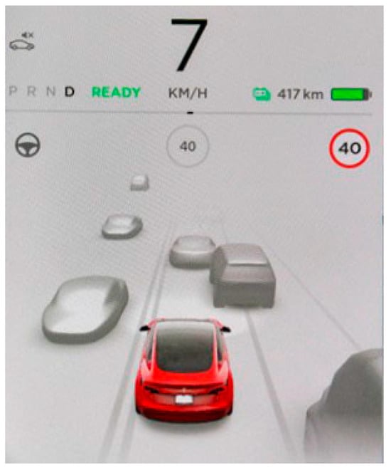
Figure 1 shows the display of the lidar signal on the main control screen of an existing car from a car manufacturer for autonomous driving. It is observed that in the application of the actual scene, the distant target vehicle outline at the opposite lane is incomplete and the imaging effect is not ideal. This proves that the overall performance in long-range imaging needs to be further improved.
This paper presents a long-range lidar optical collimation system based on shaped lasers. The shaped laser refers to the compression of the light source in two different directions, x and y, in the design of the optical system. The laser parameter used in this manuscript is a 905 nm infrared pulsed laser diode, which has different divergence angles of 33 degrees and 15 degrees in the x and y directions, respectively. A pair of asymmetric aspherical lenses, utilizing an extended polynomial, is used to collimate the light source. Both the simulation and experimental results show that the designed lens could realize relatively good collimation performance and meet the requirements of imaging research on obstacles. This work can be widely used in the field of long-range lidar detection.
3. Optical Collimation System Design
Based on the above system requirements, a single asymmetric aspherical lens scheme is first adopted for collimation. The optical system is obtained as shown in
Figure 6:
The specific parameter settings for the main lens are shown in
Table 1.
A single lens uses a polynomial, with the specific parameters set as follows: the front surface thickness is set to 8. Material is set to PMMA. Semi-Diameter is set to 2.5. The quadratic aspheric coefficient Coeff is set to −0.051, Coeff is set to −5.803 × , Coeff is set to 1.005 × , Coeff is set to 0.173, Coeff is set to −1.681 × , and Coeff is set to 5.699 × . The rear surface thickness is set to 100. Semi-Diameter is set to 2.5. The quadratic aspheric coefficient Coeff is set to −0.106, Coeff is set to −8.725 × , Coeff is set to −5.579 × , Coeff is set to −0.02, Coeff is set to 4.055 × , and Coeff is set to 2.322 × .
Based on the information in
Table 1, ray tracing simulations are performed, and the layout of light source collimated modelling is shown in
Figure 7.
Here, we use a laser source with a wavelength of 905 nm, emitted light length of 50 µm, width of 10 µm, and divergence angles of 33° and 15°, respectively.
Figure 8 shows the shape of the outgoing spot. The design requirement is to change an oval spot into a circular spot with symmetrical long and short axes after the lens collimation.
Figure 9 shows the spot diagrams at different distances from the lens using the single asymmetric aspherical lens scheme above.
It can be seen from
Figure 9 that the spot shapes are all close to circular from 100 mm to 10 m, but at 30 m, the spot diagram shows that the effects have become more dispersed and can no longer be barely circular in shape.
In order to shape the emitted spot into a circular spot at a further distance, a scheme using a pair of asymmetric aspherical lenses is adopted to optimize the collimation effects. The optical system is obtained as shown in
Figure 10.
The first face of the first lens is a sphere, and the second face is a polynomial free-form surface; the first face of the second lens is a polynomial free-form surface, and the second face is a sphere. The specific parameter settings for the main lens are shown in
Table 2.
Both the x and y axis collimators use polynomials. The specific parameters are set as follows: first, the x axis collimator is set and the front surface radius is set to 30.417. Thickness is set to 3. Material is set to PMMA. Semi-Diameter is set to 2.5. Conic’s parameter is set to 0 by default, and the surface type of the rear surface object is selected as polynomial. Thickness is set to 10 and Semi-Diameter is set to 2.5. The quadratic aspheric coefficient Coeff is set to −0.073, Coeff is set to −1.953 × , Coeff is set to −7.480 × , Coeff is set to −0.164, Coeff is set to −3.413 × , and Coeff is set to 2.788 × .
Next, the y collimator is set. Thickness is set to 3. Material is also set to PMMA. Semi-Diameter is set to 2.5. The quadratic aspheric coefficient Coeff is set to −0.017, Coeff is set to −3.404 × , Coeff is set to −5.715 × , Coeff is set to −0.069, Coeff is set to −2.588 × , and Coeff is set to −1.015 × . The rear face Radius is set to −9.089. The Thickness is set to 100. Clear Semi-Diameter is set to 2.5. Mech Semi-Diameter is set to 2.5. Conic’s parameter is set to 0 by default.
Based on the information in
Table 2, ray tracing simulations are performed, and the layout of light source collimated modelling is shown in
Figure 11.
Figure 12 shows spot diagrams at different distances from the lens after collimation. From 100 mm to 10 m, the spot shapes are all close to circular, and although signs of dispersion appear at 30 m, the overall shape can barely be circular. In contrast, a single asymmetric aspherical lens starts to show signs of dispersion at 10 m, and the dispersion effect is larger at 30 m, making it impossible to form a circular shape. Therefore, a pair of asymmetric aspherical lenses can better meet the imaging requirements at long distances compared to a single lens. Moreover, the spot size (long side × short side mm) always remains 3.2 mm × 3.2 mm, which indicates that this pair of asymmetric aspherical lenses scheme is able to achieve excellent collimation performances.
Beam collimation plays an important role in the optical lidar system, and its purpose is to collimate and shape the beam emitted by the light source with poor image quality and a large divergence angle, so as to improve the beam quality of the lidar system.
In this paper, two schemes are compared, of which
Figure 6 uses a single lens, and after simulating the ray tracing, the spot diagram shows that spot shapes have become dispersed on the image plane at a distance of 30 m. Therefore, on the basis of
Figure 6, the lens is optimized and a system with two lenses is adopted; after simulating ray tracing, the spot shape is basically circular on the image plane. Compared to a single lens, a pair of lenses can better achieve the imaging requirements at a long distance.
4. Experiments and Data Analysis
The corrected optical lenses are applied to the lidar system in
Figure 4 for verification. Firstly, the position of the ground glass is adjusted so that it is 500 mm away from the center of the lidar. The laser shoots pulsed lasers to irradiate the ground glass for a period of time, and after the light spot displayed on the ground glass is stabilized, the spot shape is photographed and recorded, as displayed in
Figure 13a. The results show that the size of the spot size (long side × short side mm) in
Figure 13a is 9 × 6 mm. In this case, the position of
Figure 13a is used as a reference point. Then, the position of the ground glass is adjusted so that the ground glass moves back 3000 mm from the center of the lidar, which means an increase in the detection distance. The position of the ground glass is adjusted every two meters and the above steps are repeated so that values at different positions are recorded. The experimental data are shown in
Figure 13 and
Table 3.
In this paper, the front and rear two lenses are used for optical design; the purpose is to collimate the x-axis and y-axis, respectively. The divergence angle is first compressed, followed by beam and collimation processing, ultimately resulting in a highly collimated homogeneous beam with a divergence angle reaching the milliradian level.
Figure 13 shows the spot imaging at different distances from the lidar. From the experimental results shown in
Figure 13, it can be seen that during the propagation of the beam from 0.5 m to 10 m, the spot on the image plane changes gradually from oval to round until it is basically in a round shape at the end. Therefore, the beam collimation lens designed in this paper has a very good effect.
Table 3 shows the spot size data. It can be seen that as the distance increases, the ratio of long and short size gets closer to 1. Based on the spot size of any two different positions, the average divergence angles in the long and short axis directions are calculated as 0.06°and 0.07°, which satisfy the project requirements.