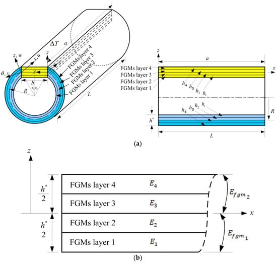
The FGM study on materials for layer 1 is SUS304, layer 2 is Si
3N
4, layer 3 is SUS304, and layer 4 is Si
3N
4. These four layers are applied in GDQ vibration simulations under the effects of
,
,
=
and with values
= 1.2 mm,
=
=
=
= 0.3 mm, and
= 1. To clearly explain the role of TSDT and shear coefficients in the thermal vibration mechanisms, they are listed in the vector expression of the typical time sinusoidal example of the four-sided simply supported boundaries for the TSDT displacements mode and can be expressed as follows:
in which , for the plate, for the shell, for the plate, and for the shell, where u and v are the tangential displacements. and are the tangential displacements in the in-surface coordinate direction, is the transverse displacement in the out-of-surface coordinate z axis-direction of the middle-plane of plate-shells. and are shear rotations for the plates. and are shear rotations for the shells. R is the middle-surface radius of the shells. is the natural frequency with respect to mode shapes m and n in subscripts. The superscript t is operating the transpose in the bold-form vector.
When
was used, the nonlinear term and
of the TSDT displacement expression for the thick-thickness material transformed into the linear term and z of the FSDT mode for the thin-thickness material. The non-dimensional shear coefficient
expressed in
Appendix A also includes the nonlinear effect of
for the thick-thickness material; thus, the advanced and varied values of
can be calculated. The calculation of
can be obtained when the values of
,
,
,
,
,
, and
T and the number of layers are given. Also, the values of
are nonlinear compared to the
value. When
used, the nonlinear
became a linear term. The impact of external thermal loads with time sinusoidal ∆
T on stress and displacement is typically theoretical supported by the vector expression and can be expressed as follows:
in which for the plates, for the shells, for the plates, for the shells, for the plates, for the shells, and
where and are the normal stresses in the plates, and are the normal stresses in the shells,, and are the shear stresses in the plates, , and are the shear stresses in the shells. , and are in-plane strains in the plates, , and are in-plane strains in the shells, and are shear strains that cannot be negligible for the thick plates, and are shear strains that cannot be negligible for the thick shells, as demonstrated using strain–displacement correlations for displacement derivatives with respect to coordinates. and are the coefficients of thermal expansion for the plates, and are the coefficients of thermal expansion for the shells, is the coefficient of thermal shear for the plates, and is the coefficient of thermal shear for the shells. with subscripts i, j = 1,2,4,5, and 6 are the stiffness values of the FGMs, e.g., , are used for the plates, , are used for the shells, and . When the values of time sinusoidal displacements are obtained, then the stress values can be calculated under the time sinusoidal ∆T. The distribution of the four-layer FGMs, e.g., Poisson’s ratio and Young’s modulus , influences the dynamic behavior of the coupled plates and cylindrical shells seen from the stiffness value of in (18) and stiffness integrals , …, , …, with respect to , , , , , , , of the plates can be seen in (5)–(15) and , …, , …, with respect to , , , , , , , , of the shells can be seen in (A10)–(A16). When the values of , , and are obtained, then the displacement and stress dynamic response values can be calculated under the time sinusoidal ∆T.
3.3. Responses of (a/2, b/2) and Versus T
Figure 4 displays response values for
(
a/2,
b/2) vs. T under 100 K, 600 K, and 1000 K with
for 1, 2, and 3 at
t = 0.1 s for
= 0.925925/mm
2 and for
= 0/mm
2, respectively, in coupled plates and circular shells with four layers,
L/
= 5,
= 100 K under
=
. Responses of
(
a/2,
b/2) compared to
T under
= 0.925925/mm
2 and
= 1 case are shown, and the maximum of
(
a/2,
b/2) is 14.420517 mm found under
T = 600 K. Values in
(
a/2,
b/2) increased from 100 K to 600 K then decreased from 600 K to 1000 K. The
(
a/2,
b/2) amplitude in
= 1 under
=
can withstand higher
T = 1000 K. Responses of
(
a/2,
b/2) compared to
T for
= 0.925925/mm
2 and
= 2 case are shown, and the maximum of
(
a/2,
b/2) is 22.746904 mm found under
T = 600 K. Values in
(
a/2,
b/2) increased from 100 K to 600 K, then decreased from 600 K to 1000 K. The
(
a/2,
b/2) amplitude in
= 2 under
=
can withstand higher
T = 1000 K. Responses of
(
a/2,
b/2) verse
T for
= 0.925925/mm
2 and
= 3 case are shown, and the maximum of
(
a/2,
b/2) is 16.266580 mm found under 600 K. Values in
(
a/2,
b/2) increased from 100 K to 600 K, then decreased from 600 K to 1000 K. The
(
a/2,
b/2) amplitude in
= 3 under
= 0.925925/mm
2 and
=
success for higher
T = 1000 K. All
(
a/2,
b/2) amplitudes under
= 0/mm
2 are in constant small values.
Figure 5 shows the
values on the center of the outer surface vs.
T for
(1, 2 and 3) at
t = 0.1 s for
= 0.925925/mm
2 and for
= 0/mm
2, respectively, in coupled plates and circular shells with four layers,
L/
= 5,
= 100 K under
=
case. The curves of
vs.
T under
= 1 case are shown, the absolute maximum value of
is 1.2357 × 10
−3 GP
a occurs at
T = 1000 K under
= 0/mm
2. Values in
increased from 100 K to 1000 K for
= 0.925925/mm
2 and
= 0/mm
2. The stress
of
= 1 under
=
cannot succeed on
T = 1000 K. The curves of
vs.
T under
= 2 case are shown, and the absolute maximum value of
is 2.1249 × 10
−3 GP
a, which occurs at
T = 1000 K under
= 0.925925/mm
2. Values in
increased from 100 K to 1000 K for
= 0.925925/mm
2 and
= 0/mm
2, respectively. The
values of
= 2 under
=
cannot succeed on
T = 1000 K. The curves of
vs.
T under
= 3 case are shown, and the absolute maximum value of
is −1.6276 × 10
−3 GP
a, which occurs at
T = 1000 K under
= 0.925925/mm
2. Values in
decreased from 100 K to 600 K and increased from 600 K to 1000 K under
= 0.925925/mm
2. The
values of
= 3 under
= 0.925925/mm
2 and
cannot succeed on
T = 1000 K. Values in
increased from 100 K to 600 K and decreased from 600 K to 1000 K under
= 0/mm
2. The
values of
= 3 under
= 0/mm
2 and
can succeed on
T = 1000 K.