
1. Introduction
The following tasks were performed on the samples in the course of investigating the functioning of the “CM insert” compounds:
- –
Strength and deformation characteristics were determined for the “CM insert” joints;
- –
Based on statistical analysis of experimental data, the load-bearing capacity and deformability of the joints were evaluated for two types of composite material.
The novelty of the study lies in the possibility of bringing the work of a traditionally flexible joint closer to rigid work and using this type of joint for gluing beams.
2. Materials and Methods
The selection of wood samples is carried out according to the general criteria of requirements for structural wood in terms of the quantity and total volume of structural features—defects, cross-grain, knots.
The characteristics of the resin during curing include a bending strength of 111 MPa, and the modulus of elasticity during bending is 4000 MPa. As is known, epoxy resins are widely used to strengthen wooden structures, including in particularly stressed areas. For the sample parameters, such as symmetrical double-cut, the joint operation of the elements in its composition is ensured by an insert based on a composite material.
The samples were fixed in a testing machine and loaded in stages until destruction. The tests were carried out on 10-ton press testing machines WDW-100E, Instron 1000 HDX (Inston Corp., Grove City, PA, USA), at standard temperature and humidity of wooden samples.
NF = min Rexp.v,Rexp.I-II
where N is the force Nmax, NI–II or Nmax; F is the chipping area, determined taking into account the number of chipping planes (n = 2). Taking into account the size of the samples, the cleavage area F = (15.0 × 9.5) * 2 = 285 cm2.
where is the temporary chipping resistance (average distribution value), MPa; = 1.65 is the quantile in the assumed statistical distribution function with a security of 0.95; = 2.33 is the quantile in the assumed statistical distribution function with a security of 0.99; and ν is the coefficient of variation according to the test results.
3. Results
The experimental data obtained during the tests are systematized, tabulated and presented in the form of graphs for both types of samples.
3.1. Test Results of B-1-Type Samples
Generalizing from the test results of the B-1 series specimens, the stress–strain state of the “CM insert” joints was based on an epoxy matrix; the average destructive load for the joint specimens was Nmax = 131.5 kN, which corresponds to the average stress at the cleavage site τcl.aver.Nmax = 4.61 MPa. The upper limit of the elastic work area of the joint was NI-II = 78.2 kN, which corresponds to the average stress at the cleavage site τcl.aver.I-II = 2.74 MPa. The average values of total deformations of the “CM insert” joint of the B-1 series were at a load of NI-II corresponding to the upper limit of the elastic work of the joint DF, I-II = 0.113 mm; the average value of the intensity of deformation growth within the elastic work of the “CM insert” joint DF, I-II/NI-II = 0.00148 mm.
which is less than the normative resistance of pure wood to chipping along the fibers Rn.p = 4.5 MPa [33].
Rcl = Σ(NF, min/F)/n = 1.58 MPa
where n = 15 is the number of B-1 series samples.
Dmax0.95 = DI-II, aver (1 + ηn ν) = 0.00148 ∗ (1 +1.65 ∗ 0.176) = 0.0019 mm.
3.2. Test Results of B-2-Type Samples
Generalizing from the test results of the B-2 series specimens, the stress–strain state of the “CM insert” compounds was based on a polyester matrix on average; the destructive load for the compound specimens was Nmax = 40.15 kN, which corresponds to the average stress at the cleavage site τcl.aver.Nmax = 1.41 MPa. The upper limit of the elastic working range of the joint was NI-II = 27.8 kN, corresponding to the average stress at the cleavage site τcl.aver.I-II = 0.975 MPa. The average values of the total deformations of the “CM insert” joint of the B-2 series at a load of NI-II, corresponding to the upper limit of the elastic work of the joint, were DF, I-II = 0.059 mm; the average value of the intensity of the deformation growth within the elastic work of the “CM insert” joint was DF, I-II/NI-II = 0.0028 mm.
which is less than the normative resistance of pure wood to chipping along the fibers Rn.p = 4.5 MPa [33].
Rcl = Σ(NF, min/F)/n = 0.465 MPa
where n = 15 is the number of samples in the B-21 series.
Dmax0.95 = DI-II, aver (1 + ηn ν) = 0.00219 ∗ (1 + 1.65 ∗ 0.178) = 0.00284 mm.
4. Discussion
The connection in question is a type of traditionally flexible connection; however, the materials used to ensure joint operation under load allow this connection to be transferred to the rigid category, where the shear deformation of the connected elements is negligible, compared to the linear dimensions of the samples.
A comparative assessment of the bearing capacity and deformability of the “CM insert” compounds made on the basis of an epoxy matrix (B-1 series) and a polyester matrix (B-2 series) was performed in relation to the compounds of the B-2 series. We compared the “CM insert” compound on a polyester matrix with the “CM insert” compound on an epoxy matrix and found the following:
- –
The destructive load Nmax and temporary chipping resistance Rclt is 3.27 times greater;
- –
The load of NI-II, corresponding to the upper boundary of the elastic region of the “CM insert” joint, is 2.8 times greater;
- –
- –
The deformability of the “CM insert” DF and I-II/NI-II joint at the level of the upper boundary of the elastic work area is 1.48 times less;
- –
The normative cleavage resistance Rcln of the joint “CM insert” is 4 times greater;
- –
The calculated cleavage resistance Rcl of the joint “CM insert” is 4.7 times greater.
5. Recommendations for the Calculation of Joints of Wooden Elements with a Composite Material Based on Fiberglass
For each type of joint, strength characteristics were determined as a function of the stress state and the type of composite material used in the joint, as well as deformation characteristics, which determine the deformability within the calculated load-bearing capacity and the elastic operation of the joints.
The main normalized strength characteristics of the “CM insert” joint are the calculated joint resistances determined using the method and taking into account the statistical variability of the strength indicators with a confidence level of at least 0.95 for standard resistances and 0.99865 for calculated resistances based on the test results of the joint samples. The maximum probable deformability of the “CM insert” joint was also determined from the test results with a confidence level of 0.95.
Strength and deformation characteristics corresponding to the calculated bearing capacity of the joints have been established for the “CM insert” joints:
The temporary chipping resistance:
- –
For a compound on an epoxy matrix, Rclt = 4.61 MPa;
- –
For a compound on a polyester matrix, Rclt = 1.41 MPa.
- –
For a compound on an epoxy matrix, Rcl = 1.58 MPa with a coefficient of variation V = 0.191;
- –
For a compound on a polyester matrix, Rcl = 0.465 MPa with a coefficient of variation V = 0.267.
The normative chipping resistance with a confidence probability (security) at a minimum of Rd = 0.95 for the loading mode “A” corresponding to a linearly increasing load during standard machine tests:
- –
For connection on an epoxy matrix, Rcln = 3.21 MPa;
- –
For a compound on a polyester matrix, Rcln = 0.806 MPa.
The calculated chipping resistance with a confidence probability (security) at a minimum of Rd = 0.99865 for the loading mode “A” corresponding to a linearly increasing load during standard machine tests:
- –
For connection on an epoxy matrix, Rcl = 2.63 MPa
- –
For connection on a polyester matrix, Rcl = 0.558 MPa;
The deformability of joints within the calculated bearing capacity:
- –
For joints type 1 and type 3, DF/Nd = 0.0021 mm/kN;
- –
For connection type 2, DF/Nd = 0.0031 mm/kN.
[TclCM] = RclCM ∗ LCM ∗ binsert,
where RclCM = Rcl/(γm ∗ γmn) is the calculated resistance to cleavage of the “CM insert” joint; RclCM—see paragraph 8.64; γm = 1.1 is the coefficient of reliability of the composite material in the “CM insert” joint; γmn is the coefficient of reliability according to the method of manufacture of the joint, LCM = LO − 2 ∗ 50 mm is the estimated length of the “CM insert”; and binsert is the width of the strip of the composite liner in the joint.
The length of the “CM insert” joint LO when developing a new wooden element of composite section should be at least one-quarter of the span of the element being created. The working length of the “CM insert” joint LO when restoring an existing wooden element should be allocated according to the size of the restored section on the wooden structure but not less than one-half of the length of the restored section.
We calculated the chipping resistance of the composite material and the results are as follows:
- –
For “CM insert” joints based on epoxy matrix and fiberglass, T13 Rcl = 1.58 MPa;
- –
For “CM insert” compounds based on polyester matrix and fiberglass, T13 Rcl = 0.465 MPa;
6. Conclusions
In total, 15 samples were tested for each type of compound.
- 2.
For “CM insert” compounds using composite materials based on an epoxy matrix (B-1) and a polyester matrix (B-2), the following results were obtained:
The temporary cleavage resistance is Rclt = 4.61 MPa and 1.41 MPa;
The average value of the calculated chipping resistance is Rcl = 1.58 MPa and 0.465 MPa with coefficients of variation V = 0.191 and 0.267;
The normative cleavage resistance with a confidence probability (security) at a minimum Rd = 0.95 for the loading mode “A” corresponding to a linearly increasing load under standard machine tests is Rcln = 3.21 MPa and 0.806 MPa;
The calculated chipping resistance with a confidence probability (security) at a minimum of Rd = 0.99 for the loading mode “A” corresponding to a linearly increasing load at standard machine tests is Rcl = 2.63 MPa and 0.558 MPa;
The maximum probable deformation at the load level corresponding to the upper boundary of the NI-II elastic region is Dmax 0.95 = 0.0019 mm and 0.0028 mm.
- 3.
A comparative assessment of the bearing capacity and deformability of the “CM insert” compounds revealed that the strength characteristics of the epoxy matrix-based compound are 2.8–4.7 times greater than those of the polyester matrix-based compounds, while the deformability is 1.48 times less.
- 4.
For use in load-bearing wooden structures, “CM insert” compounds based on a KDA-M epoxy matrix with Etal-45 hardener and T-13 fiberglass are recommended.
- 5.
As a result, the proposed connection made it possible to eliminate mutual shear deformations from the connection operation and proved the rigidity of the connection and the viability of the composite material used.
Author Contributions
Conceptualization, A.T.; methodology, A.T.; software, L.N. and K.A.; validation, L.N. and K.A.; formal analysis, A.T.; investigation, A.T., L.N. and K.A.; resources, A.T. and L.N.; data curation K.A.; writing—original draft preparation, L.N. and K.A.; writing—review and editing, A.T.; visualization, L.N.; supervision, A.T.; project administration, A.T.; funding acquisition, A.T. All authors have read and agreed to the published version of the manuscript.
Funding
This research is funded by a grant issued by the National Research Moscow State University of Civil Engineering as a result of a competition among the lecturers for implementation of fundamental and applied scientific research (R&D) by the teams of NRU MGSU researchers (Order 527/130-22/06/2022-project No. 30). The research was funded by the National Research Moscow State University of Civil Engineering (grant for fundamental and applied scientific research, project No. 30-234/130).
Data Availability Statement
The data presented in this study are available on request from the corresponding author.
Conflicts of Interest
The authors declare no conflicts of interest.
References
- Chibrikin, D.A.; Lukin, M.V.; Lukina, A.V.; Tyurikova, T.V.; Roshchina, S.I. Numerical Study of the Stress-Strain State of a Modified Wooden Beam. Russ. For. J. 2022, 3, 167–178. [Google Scholar] [CrossRef]
- Borri, A.; Corradi, M.; Speranzini, E. Reinforcement of Wood with Natural Fibers. Engineering 2013, 53, 1–8. [Google Scholar] [CrossRef]
- Yusof, A.; Rahman, A.B. Flexural Strengthening of Timber Beams Using Carbon Fibre Reinforced Polymer. Int. J. Appl. Eng. Res. 2017, 12, 348–358. [Google Scholar]
- Yasemin, S.T.; Semsettin, K. Experimental and Numerical Investigation of Flexural Properties of Larch Beams Reinforced with Different Layer Numbers. J. Constr. 2024, 23, 47–57. [Google Scholar] [CrossRef]
- Rutman, U.L.; Meleshko, V.A. The Generalization of the Flexibility Method for Elastoplastic Computation of Rod Systems. Mater. Phys. Mech. 2017, 31, 67–70. [Google Scholar]
- Kozinetc, K.G.; Kärki, T.; Barabanshchikov, Y.G.; Lahtela, V.; Zotov, D.K. Mechanical Properties of Sustainable Wooden Structures Reinforced with Basalt Fiber Reinforced Polymer. Mag. Civ. Eng. 2020, 100, 10012. [Google Scholar]
- Toğay, A.; Döngel, N.; Söğütlü, C.; Ergin, E.; Uzel, M.; Güneş, S. Determination of the Modulus of Elasticity of Wooden Construction Elements Reinforced with Fiberglass Wire Mesh and Aluminum Wire Mesh. BioResources 2017, 12, 2466–2478. [Google Scholar] [CrossRef]
- Trummer, A.; Wilhelm, F. Zuschnitt 17. Holz Proholz. Austria 2005, 11, 24. [Google Scholar]
- Blaß, H.; Romani, M. Biegezugverstärkung von Brettschichtholz mit CFK- und AFK-Lamellen. Bautechnik 2002, 79, 216–224. [Google Scholar]
- Blaß, H.; Romani, M. Tragfähigkeitsuntersuchungen an Verbundträgern aus BS-Holz und Faserverbundkunststoff-Lamellen. Eur. J. Wood Wood Prod. 2001, 59, 364–373. [Google Scholar] [CrossRef]
- Lisyatnikov, M.S.; Glebova, T.O.; Ageev, S.P.; Ivaniuk, A.M. Strength of Wood Reinforced with a Polymer Composite for Crumpling across the Fibers. IOP Conf. Ser. Mater. Sci. Eng. 2020, 896, 012062. [Google Scholar] [CrossRef]
- Zachary, C.; Kavan, S. Feasibility of Strengthening Glulam Beams with Prestressed Basalt Fibre Reinforced Polymers; Chalmers University of Technology, Göteborg, Sweden, 2012.
- Stoyanov, V.O. Strength and Deformability of Bent Wooden Elements Reinforced with Polymer Composites. Master’s Thesis, TSNIISK Named after V.A. Kucherenko, Moscow, Russia, 2018. (In Russian). [Google Scholar]
- Rajčić, V.; Perković, N.; Damjanović, D.; Barbalić, J. Influence of Friction on the Behavior and Performance of Prefabricated Timber–Bearing Glass Composite Systems. Sustainability 2022, 14, 1102. [Google Scholar] [CrossRef]
- Sokołowski, P.K.; Kossakowski, P.G. Static Analysis of Wooden Beams Strengthened with FRCM-PBO Composite in Bending. Materials 2023, 16, 1870. [Google Scholar] [CrossRef] [PubMed]
- Krstevska, L.; Tashkov, L.; Rajcic, V.; Zarnic, R. Shaking Table Test of Innovative Composite Panel Composed of Glued Laminated Wood and Bearing Glass. In Proceedings of the 15th World Conference on Earthquake Engineering, Lisbon, Portugal, 24–28 September 2012; pp. 1–10. [Google Scholar]
- Žarnić, R.; Rajčić, V.; Kržan, M. Response of Laminated Glass-CLT Structural Components to Reverse-Cyclic Lateral Loading. Constr. Build. Mater. 2020, 235, 117509. [Google Scholar] [CrossRef]
- Ashari, B.; Guan, Z.W.; Kitamori, A.; Jung, K.; Komatsu, K. Structural behaviour of glued laminated timber beams pre-stressed by compressed wood. Constr. Build. Mater. 2012, 29, 24–32. [Google Scholar] [CrossRef]
- Antolinc, D.; Rajčić, V.; Žarnić, R. Analysis of Hysteretic Response of Glass Infilled Wooden Frames. J. Civ. Eng. Manag. 2014, 20, 600–608. [Google Scholar] [CrossRef]
- Wellersho, F.; Sedlacek, G. Stabilization of Building Envelopes with the Use of the Glazing. In Proceedings of the Glass Processing Days, Tampere, Finland, 17–20 June 2005; pp. 281–283. [Google Scholar]
- Kay-Uwe, S. Hochleistungskunststoffe für die Tragwerksverstärkung von Holzkonstruktionen im Bestand. Z. Nachhalt. Bau. Bauwerkserhaltung Denkmalpfl. Sonderdr. Bausubstanz 2010, 4, 38–43. [Google Scholar]
- Tamrazyan, A.; Alekseytsev, A. Evolutionary optimization of reinforced concrete beams, taking into account design reliability, safety and risks during the emergency loss of supports. E3S Web Conf. 2019, 97, 4005. [Google Scholar] [CrossRef]
- CNR-DT 201 Advisory Committee on Technical Recommendations for Construction. Italy. 2005. p. 58. Available online: https://www.cnr.it/en/node/2637 (accessed on 3 October 2024).
- Franke, S.; Franke, B.; Harte, A.M. Failure Modes and Reinforcement Techniques for Timber Beams—State of the Art. Constr. Build. Mater. 2015, 97, 2–13. [Google Scholar] [CrossRef]
- Zhou, A.; Tam, L.-h.; Yu, Z.; Lau, D. Effect of Moisture on the Mechanical Properties of CFRP–Wood Composite: An Experimental and Atomistic Investigation. Compos. Part B Eng. 2015, 71, 63–73. [Google Scholar] [CrossRef]
- Tam, L.-h.; Zhou, A.; Yu, Z.; Qiu, Q.; Lau, D. Understanding the Effect of Temperature on the Interfacial Behavior of CFRP-Wood Composite via Molecular Dynamics Simulations. Compos. Part B Eng. 2017, 109, 227–237. [Google Scholar] [CrossRef]
- EN 1995-1-1; Eurocode 5: Design of Timber Structures—Part 1-1: General—Common Rules and Rules for Buildings. The European Committee for Standardization: Brussels, Belgium, 1995.
- EN 1995-1-2; Eurocode 5: Design of Timber Structures—Part 1-2: General—Structural Fire Design. The European Committee for Standardization: Brussels, Belgium, 1995.
- EN 1995-2; Design of Timber Structures—Part 2: Bridges. The European Committee for Standardization: Brussels, Belgium, 1995.
- DIN EN 408-2012; Timber Structures—Structural Timber and Glued Laminated Timber—Determination of Some Physical and Mechanical Properties. Deutsches Institut für Normung: Berlin, Germany, 2012.
- ACI 440R-96; State-of-the-Art Report on Fiber Reinforced Plastic (FRP) Reinforcement for Concrete Structures, Reported by ACI Committee. ACI Committee: Farmington Hills, MI, USA, 2002.
- SP 64.13330.2017; Wooden Structures. Updated Version of SNiP II-25-80. Ministry of Construction and Housing and Communal Services of the Russian Federation: Moscow, Russia, 2018.
- Ivanov, Y.M. Recommendations for Testing Joints of Wooden Structures; TSNIISK Named after V.A. Kucherenko: Moscow, Russia; Stroyizdat: Moscow, Russia, 1981. [Google Scholar]
- Corradi, M.; Borri, A.; Righetti, L.; Speranzini, E. Uncertainty analysis of FRP reinforced timber beams. Compos. Part B Eng. 2017, 113, 174–184. [Google Scholar] [CrossRef]
- Shekarchi, M.; Farahani, E.M.; Oskouei, A.V. Effect of seawater on pull-out behavior of glued-in single rods set parallel to the grain of timber joints. Constr. Build. Mater. 2019, 222, 342–357. [Google Scholar] [CrossRef]
- De Luca, V.; Marano, C. Prestressed glulam timbers reinforced with steel bars. Constr. Build. Mater. 2012, 30, 206–217. [Google Scholar] [CrossRef]
- Schober, K.U.; Tannert, T. Hybrid connections for timber structures. Wood Prod. 2016, 74, 369–377. [Google Scholar] [CrossRef]
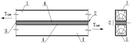
Connection of wooden elements with a composite material based on an epoxy matrix and fiberglass with a liner installed between adjacent planes of the elements to be connected—“CM insert”: 1—wooden elements to be connected; 2—welding seam; 3—composite material, 4—adhesive layer.
Figure 1.
Connection of wooden elements with a composite material based on an epoxy matrix and fiberglass with a liner installed between adjacent planes of the elements to be connected—“CM insert”: 1—wooden elements to be connected; 2—welding seam; 3—composite material, 4—adhesive layer.
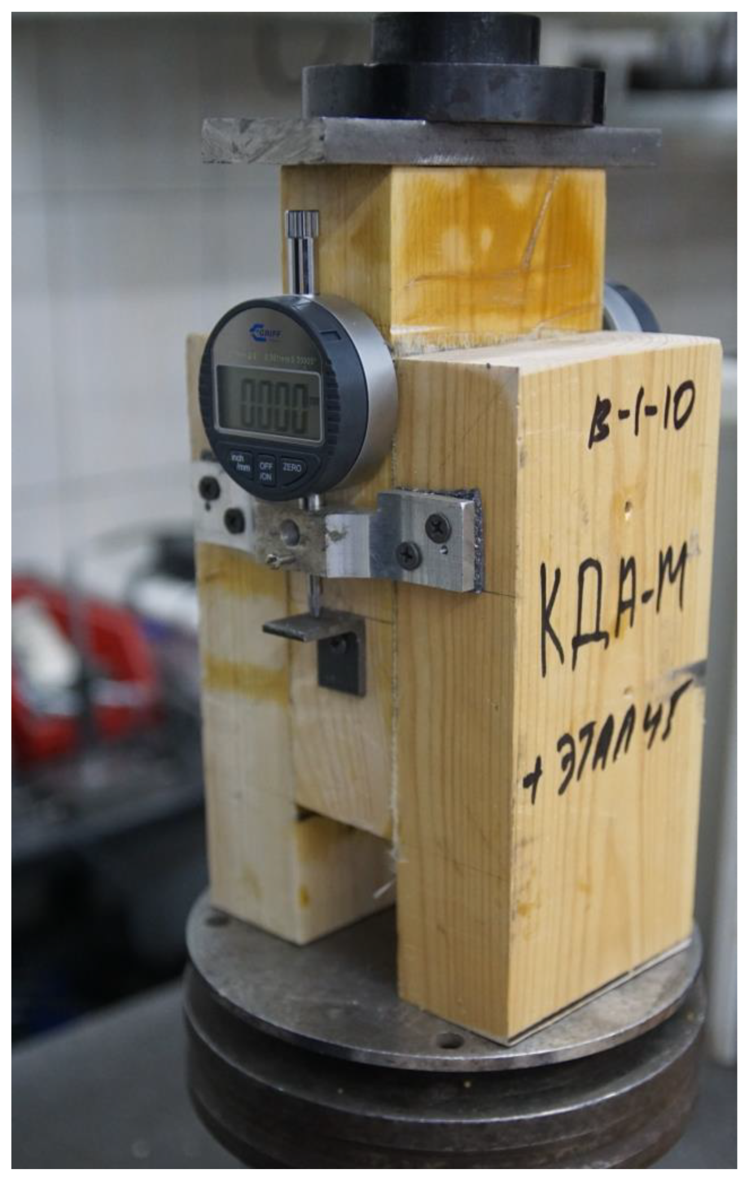
B-1-type sample view during testing.
Figure 2.
B-1-type sample view during testing.
Graphs of the “deformation load” dependence of B-1-type samples based on an epoxy matrix.
Figure 3.
Graphs of the “deformation load” dependence of B-1-type samples based on an epoxy matrix.

Graphs of deformations of full DF [mm] samples of the “CM insert” B-2 series compound based on a polyester matrix.
Figure 4.
Graphs of deformations of full DF [mm] samples of the “CM insert” B-2 series compound based on a polyester matrix.
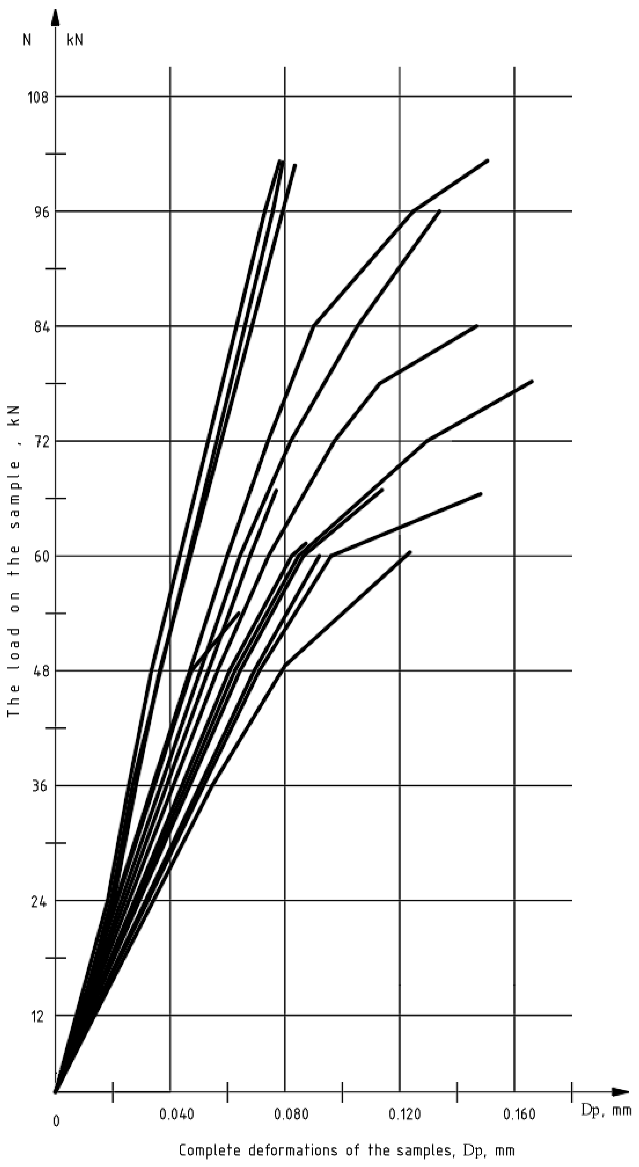
Table 1.
The bearing capacity and deformability of the samples of the “CM insert” joint. B-1 series.
Table 1.
The bearing capacity and deformability of the samples of the “CM insert” joint. B-1 series.
| № sam. | Τdestr = = Nmax/F, MPa | EBC of the Connection, Rexp | Сhipping Resistance Rcl = Rexp/F | Joint Deformations | |||
|---|---|---|---|---|---|---|---|
| Nmax kN | NI-II kN | Nmax MPa | NI-II MPa | DF, I-II mm | DF, I-II/NI-II mm/kN | ||
| 1 | 2 | 3 | 4 | 5 | 6 | 7 | 8 |
| В-1-1 | 3.16 | 30.2 | 50.8 | 1.06 | 1.78 | 0.157 | 0.00238 |
| В-1-2 | 5.16 | 51.4 | 71.5 | 1.80 | 2.51 | 0.125 | 0.00134 |
| В-1-3 | 4.53 | 44.0 | 64.6 | 1.54 | 2.27 | 0.139 | 0.00165 |
| В-1-4 | 4.21 | 40.8 | 46.2 | 1.43 | 1.62 | 0.091 | 0.00152 |
| В-1-5 | 3.88 | 37.6 | 46.2 | 1.32 | 1.62 | 0.099 | 0.00165 |
| В-1-6 | 4.40 | 42.8 | 50.8 | 1.50 | 1.78 | 0.089 | 0.00134 |
| В-1-7 | 4.95 | 48.2 | 60.0 | 1.69 | 2.11 | 0.110 | 0.00140 |
| В-1-8 | 5.47 | 53.4 | 73.8 | 1.87 | 2.59 | 0.087 | 0.00091 |
| В-1-9 | 4.84 | 47.1 | 55.4 | 1.65 | 1.94 | 0.100 | 0.00139 |
| В-1-10 | 4.42 | 42.9 | 60.0 | 1.51 | 2.11 | 0.117 | 0.00149 |
| В-1-11 | 4.00 | 38.8 | 50.8 | 1.36 | 1.78 | 0.112 | 0.00170 |
| В-1-12 | 5.79 | 56.7 | 73.8 | 1.99 | 2.59 | 0.116 | 0.00120 |
| В-1-13 | 5.86 | 57.4 | 73.8 | 2.01 | 2.59 | 0.127 | 0.00132 |
| В-1-14 | 3.16 | 30.3 | 50.8 | 1.06 | 1.78 | 0.103 | 0.00156 |
| В-1-15 | 5.37 | 52.4 | 73.8 | 1.84 | 2.59 | 0.133 | 0.00139 |
| Aver. | Rclt = 4.61 | 44.94 | 60.15 | 1.58 | 2.11 | 0.113 | 0.00148 |
Table 2.
Statistical processing of test results of B-1-type samples of the “CM insert“ connection.
Table 2.
Statistical processing of test results of B-1-type samples of the “CM insert“ connection.
| Type of Load and Deformation | Meas. Units | M | S | V % | m | p % |
|---|---|---|---|---|---|---|
| Nmax | kN | 131.48 | 24.21 | 18.4 | 6.25 | 4.75 |
| Rclt = τaver = Nmax/F | MPa | 4.61 | 0.85 | 18.4 | 0.22 | 4.75 |
| NI-II | kN | 78.2 | 14.18 | 18.1 | 3.66 | 4.68 |
| (DF, I-II/NI-II) * | mm/kN | 0.00148 | 0.00032 | 21.4 | 0.00008 | 5.53 |
| Rcl = NF, min/F | MPa | 1.58 | 0.30 | 0.191 | 0.08 | 4.92 |
Table 3.
Bearing capacity and deformability of B-2-type samples.
Table 3.
Bearing capacity and deformability of B-2-type samples.
| № sam. | Τdestr * = = Nmax/F, MPa | EBC *** of the Connection, Rexp | Сhipping Resistance Rcl = Rexp/F | Joint Deformations | |||
|---|---|---|---|---|---|---|---|
| Nmax kN | NI-II kN | Nmax MPa | NI-II MPa | DF, I-II mm | DF/NI-II mm/kN | ||
| 1 | 2 | 3 | 4 | 5 | 6 | 7 | 8 |
| В-2-1 | 1.15 | 10.75 | 18.46 | 0.38 | 0.65 | 0.070 | 0.0038 |
| В-2-2 | 1.13 | 10.52 | 16.15 | 0.37 | 0.57 | 0.065 | 0.0040 |
| В-2-3 | 1.37 | 12.84 | 18.46 | 0.45 | 0.65 | 0.060 | 0.0032 |
| В-2-4 | 1.28 | 12.04 | 18.46 | 0.42 | 0.65 | 0.047 | 0.0025 |
| В-2-5 | 1.58 | 14.89 | 27.69 | 0.52 | 0.97 | 0.053 | 0.0019 |
| В-2-6 | 1.86 | 17.59 | 27.69 | 0.62 | 0.97 | 0.072 | 0.0026 |
| В-2-7 | 1.16 | 10.83 | 20.77 | 0.38 | 0.73 | 0.082 | 0.0039 |
| В-2-8 | 1.47 | 13.87 | 20.77 | 0.49 | 0.73 | 0.062 | 0.0030 |
| В-2-9 | 1.26 | 11.82 | 20.77 | 0.41 | 0.73 | 0.057 | 0.0027 |
| В-2-10 | 1.79 | 16.91 | 23.08 | 0.59 | 0.81 | 0.064 | 0.0028 |
| В-2-11 | 1.16 | 10.82 | 18.46 | 0.38 | 0.65 | 0.062 | 0.0033 |
| В-2-12 | 2.32 | 22.04 | 27.69 | 0.77 | 0.97 | 0.049 | 0.0018 |
| В-2-13 | 1.58 | 14.86 | 27.69 | 0.52 | 0.97 | 0.056 | 0.0020 |
| В-2-14 | 1.08 | 10.05 | 16.15 | 0.35 | 0.57 | 0.045 | 0.0028 |
| В-2-15 | 0.95 | 8.80 | 18.46 | 0.31 | 0.65 | 0.046 | 0.0025 |
| Aver. | Rclt ** = 1.409 | 13.243 | 21.385 | 0.465 | 0.750 | 0.059 | 0.0028 |
Table 4.
Statistical processing of test results of samples of “CM insert” compound. B-2 series.
Table 4.
Statistical processing of test results of samples of “CM insert” compound. B-2 series.
| Type of Load and Deformation | Meas. Units | M | S | V % | m | p % |
|---|---|---|---|---|---|---|
| Nmax | kN | 40.147 | 10.406 | 0.259 | 2.687 | 6.7 |
| Rclt = τaver = Nmax/F | MPa | 1.409 | 0.365 | 0.259 | 0.094 | 6.692 |
| N I-II | kN | 27.80 | 5.609 | 0.202 | 1.448 | 5.209 |
| (DF, I-II/NI-II) * | mm/kN | 0.0219 | 0.00054 | 0.2445 | 0.00014 | 6.314 |
| Rcl = NF, min/F | MPa | 0.465 | 0.124 | 0.267 | 0.032 | 6.882 |
Disclaimer/Publisher’s Note: The statements, opinions and data contained in all publications are solely those of the individual author(s) and contributor(s) and not of MDPI and/or the editor(s). MDPI and/or the editor(s) disclaim responsibility for any injury to people or property resulting from any ideas, methods, instructions or products referred to in the content. |
Source link
Alexander Tusnin www.mdpi.com