
1. Introduction
In the wave of the energy revolution in the 21st century, electrochemical energy storage technology, as a key link to promote the transformation of the energy structure and achieve the popularization of clean energy, has been widely researched around the world [1,2]. As a potential electrochemical energy storage device, the sodium-ion battery has become an important supplement to the lithium battery because of its advantages of abundant resources, low cost and environmental friendliness [3]. In the research and development of sodium-ion batteries, the selection and optimization of anode materials play a crucial role in improving the overall performance of the battery and promoting its commercialization process. Hard carbon (HC), as a promising candidate for sodium-ion battery anode materials, exhibits unique structural and performance features. These features enable it to reversibly intercalate sodium ions and achieve a specific capacity of 250–320 mAh g−1, making it a primary material for commercial sodium-ion batteries [4,5,6,7,8].
However, HC anodes still face several challenges in practical applications, including slow ion transport rates and poor electrode/electrolyte interface stability. In order to alleviate this problem, researchers have improved the structure and properties of HC through methods such as heteroatom doping [9,10] and structural adjustment [11] to improve the electrical conductivity or enhance the stability of carbon materials. However, atomic doping relies on complex synthesis processes, which make it difficult to precisely control the atomic conditions, leading to uneven doping and, consequently, differences in the performance of various parts of the hard carbon material. Furthermore, the complexity of the process increases both the difficulty of material preparation and the cost [12]. In addition to material modification, regulating electrolyte composition or introducing electrolyte additives are also effective ways to improve the stability of the HC anode. Similar to lithium-ion batteries, the electrolyte of sodium-ion batteries not only conducts ions between electrodes, but also forms a solid electrolyte interface (SEI) film on the surface of the anode [13]. However, the SEI film produced by traditional ester solvent-based electrolytes is thick and unstable [14], and ether solvent-based electrolytes will decompose under high pressure [15,16]. The HC/electrolyte interface is unstable, which easily lead to the decomposition of electrolyte and the corrosion of electrode material, thus shortening battery cycle life [17]. The introduction of additives into the electrolyte that can preferentially undergo reduction reactions on the surface of HC can guide the directional growth of the SEI film and alter its thickness, stability, and interface impedance [18,19]. Thus, to enhance the development of SIBs with a long cycle life, it is urgent to develop electrolyte additives that can stabilize the HC anode.
Ionic liquids (ILs) possess unique properties, including a low melting point, high thermal and chemical stability, high ionic conductivity, a wide electrochemical window, non-volatility, and non-flammability, and are an ideal alternative to organic solvents or electrolyte additives for sodium-ion batteries, which can improve the safety, energy/power density, and cycle stability of batteries. ILs can be used alone or as an additive in electrolytes [20,21]. For example, Zhao et al. developed a novel imidazolium-based ILs (AMMEIMTFSI) as an additive (the optimal content is 10 vol%) for carbonate electrolyte to enhance the antioxidant capacity of the electrolyte (withstand 5V) [22]. Luciana et al. used a pyrrole-based ILs (PYR14FSI) as the independent solvent to dissolve NaTFSI salt and form IL-based electrolyte. This IL-based electrolyte formed a dense CEI film on the cathode surface, which reduced the dissolution of manganese ions and effectively improved the cycle stability of the cathode material [23]. Atsushi et al. studied the electrochemical characteristics of HC anode in NaFSA-C1C3pyrFSA electrolyte, and proved that ILs can promote the insertion/removal of sodium ions and inhibit dendrite growth, thus significantly improving the cycle performance and rate performance of the HC anode [24]. Meng et al. used allylbutylpiperidine-containing ILs (pp14FSI) as an electrolyte additive (the optimal content is 15 vol%) and found that it significantly enhanced the cycling stability and high temperature performance for HC anodes [25]. The above research has shown that designing IL-based electrolytes is an effective strategy to enhance the electrode stability and rate performance of sodium-ion batteries.
Our recent study found that the di-cationic IL (the number of methylene groups that bridge the two cations is 4) has higher electrochemical stability and chemical/physical adsorption compared to ordinary mono-cationic ILs [26,27]. Therefore, in this article, we report a novel di-cationic ILs additive, C4di[mPy].di[PF6], for enhancing the cycling stability of HC anode. The introduction of C4di[mPy].di[PF6] increases the concentration of PF6−, which helps form an NaF-rich SEI film. Additionally, since C4di[mPy]2+ has the lowest LUMO energy level, it could be preferentially reduced, leading to the formation of a stable, thin, and dense SEI film. Based on these effects, the obtained SEI film improved the interface stability of HC anode, reduced the electrolyte–anode material side reactions, and improved the long-cycle stability of the battery. As a result, the Na||HC half-cell with C4di[mPy].di[PF6] showed a capacity retention rate of 90.4% after 400 cycles at 100 mA g−1 and 82% after 500 cycles at 300 mA g−1. In addition, the capacity retention rate of the vanadium phosphate sodium (NVP)||HC full cell has also been significantly improved.
3. Results and Discussion
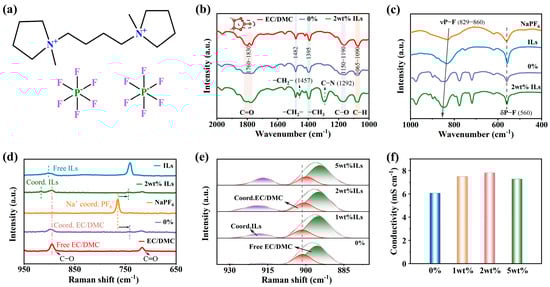
Figure 1a shows the structural diagram of C4di[mPy].di[PF6], where the cation structure is formed by connecting two methylpyrrolidine-cation groups together through an alkyl skeleton. The cation forms an ion pair with two PF6− ions through electrostatic interactions, forming a stable ionic liquid. The unique structure of C4di[mPy].di[PF6] directly influences the properties of the electrolyte. Firstly, the behavior and function of ILs in electrolytes were analyzed using FTIR spectra and Raman spectra. As shown in Figure 1b, 0% represents 1M NaPF6/EC:DMC (1:1) electrolyte, and 2 wt% ILs represents 1M NaPF6/EC:DMC (1:1) + 2 wt% C4di[mPy].di[PF6] electrolyte. It can be seen that the C=O peak in the EC/DMC solvent is relatively sharp. However, in the 0% and 2 wt% electrolyte, the C=O peak becomes broader, especially in the electrolyte containing 2 wt% ILs, which may be affected by the effect of hydrogen bonding. Meanwhile, it can be clearly seen from the IR spectra that after adding IL additives, obvious characteristic peaks appear at 1457 cm−1 and 1292 cm−1, corresponding to the -CH2– bond and C-N bond in C4di[mPy]2+, respectively, indicating that the IL additives have been uniformly dispersed in the electrolyte. Of particular note is that the characteristic peak located at 1292 cm−1 has a strong and relatively sharp intensity, indicating the presence of a large number of ionic liquid ions (N+) in the electrolyte, which is beneficial for improving the ionic conductivity of the electrolyte. As shown in Figure 1c, it was found that the addition of ILs resulted in a blue shift in the P-F stretching vibration peak at 829 cm−1, which demonstrated an enhanced interaction between Na+ and PF6−. As shown in Figure 1d, in the Raman spectra, after NaPF6 was dissociated in EC/DMC solvent and solvent containing 2 wt% ILs, the P-F peak in PF6− shifted from 765 cm−1 to 742 cm−1 and 745 cm−1, respectively. The displacement of the P-F peak in electrolyte containing 2 wt% ILs is slightly smaller, indicating that there is stronger binding between Na+ and PF6− than that in the electrolyte without ILs [28]. In addition, compared with the spectra of 0% electrolyte and EC/DMC solvent, it was found that the characteristic peak at 895 cm−1 undergoes a blue shift after EC/DMC solvent binding with Na+, indicating that Na+ and EC/DMC solvent have strong binding force. However, in the electrolyte containing 2 wt% ILs, the characteristic peak at this point shows almost no shift, indicating that the addition of ILs weakens the interaction between Na+ and EC/DMC solvent. Pure ILs have another characteristic peak at 902 cm−1, but this characteristic peak exhibits a blue shift in the electrolyte containing 2 wt% ILs, indicating a strong interaction between a certain component in the electrolyte and C4di[mPy].di[PF6]. From Figure 1e, it can be seen that as the concentration of ILs increases, the red shift of the characteristic peak of EC/DMC solvent at 895 cm−1 gradually increases, indicating that the interaction between Na+ and the EC/DMC gradually decreases. In addition, conductivity tests were carried out on different electrolytes (Figure 1f), and it can be seen that the ionic conductivity of the electrolyte was significantly increased by the addition of C4di[mPy].di[PF6]. Because ILs are composed of asymmetric anions and cations, the interaction between the ions is weak, so they can be completely dissociated into free anions and cations in organic solvents, thus enhancing the conductivity of the electrolyte [29,30].
As shown in Figure 2a, constant current charge–discharge tests were conducted on Na||HC half-cell using different electrolytes at a current density of 15 mA g−1. The capacity of the HC anode in the base electrolyte was lower and less stable than that in the electrolyte containing ILs. The initial reversible specific capacity of HC anode in electrolyte containing 2 wt% ILs was 14.7% higher than that in the base electrolyte. After 100 cycles, the capacity of the HC anode in electrolytes containing ILs remained above 300 mAh g−1. Figure S5a shows the EIS spectrum and corresponding fitting curve of the Na||HC half-cell after 10 cycles. Compared with the base electrolyte, the SEI impedance (RSEI) and charge transfer impedance (Rct) of electrolyte containing C4di[mPy].di[PF6] are significantly reduced (Figure S5b). Above, by comparing the three electrolytes containing different proportions of additives, it is found that the electrolyte containing 2 wt% ILs has the highest ionic conductivity, the highest capacity and cycling stability, and lowest impedance value. Therefore, the electrolyte additive containing 2 wt% ILs is chosen as the best proportion. Further characterization and discussion will focus on the comparison between the base electrolyte and the electrolyte containing 2 wt% C4di[mPy].di[PF6].
In order to prove that the introduction of C4di[mPy].di[PF6] has a positive effect on HC anode rather than Na tablet, we conducted a comparative study on Na||Na symmetric cells using electrolytes with and without ILs additive, and the results are depicted in Figure S6. It is evident that the C4di[mPy].di[PF6] only reduces the polarization degree of the Na||Na symmetric cell, but has little effect on the stability improvement, which proves that the performance improvement of the Na||HC half-cell is due to the enhancement of the stability of the HC anode by the additive. In order to further explore the mechanism of action behind this stability enhancement, an in-depth analysis of the HC anode is necessary. As shown in Figure 2b, the wettability of the base electrolyte and the additive electrolyte to the HC anode were tested. The traditional electrolyte usually faces difficulty in wetting the electrode quickly and evenly, resulting in an increased internal resistance of the battery and affecting the transmission efficiency of sodium ions [31]. It can be seen that the contact angle of the traditional electrolyte on the surface of HC anode is as high as 31°, and the contact angle only decreased to 28.2° after 10 s of wetting (Figure S7). In contrast, the contact angle of the electrolyte with additives decreased to 14.7° after 10 s of wetting. The decrease in contact angle proves that the addition of ILs improves the wetting of the electrolyte to the HC anode and helps the electrolyte penetrate into HC microstructure better. In order to further evaluate the transport dynamics of Na+ at the electrode/electrolyte interface, the Na+ diffusion coefficients during the discharging and charging processes of HC in the two electrolytes were determined using the constant current intermittent titration technique (GITT), and the result is shown in Figure 2c,d and Figure S8. It is evident that the DNa+ value in the electrolyte containing C4di[mPy].di[PF6] is consistently higher than that in the electrolyte without additives throughout the entire charging and discharging cycle, indicating that the C4di[mPy].di[PF6] additive enhanced the Na+ transfer kinetics and ionic diffusion coefficient. In addition, according to the CV curves (Figure 2e,f) of HC anode obtained at various scan rates in two electrolytes, the corresponding polarization curves were drawn, as shown in Figure 2g. It is observed that the polarization of HC in the electrolyte containing 2 wt% ILs is lower than that in electrolytes without additive, and this difference became more obvious with the increase in the scanning rate, indicating that HC anode has excellent sodium storage kinetics in the electrolyte containing C4di[mPy].di[PF6].
In order to comprehensively evaluate the stability of the HC anodes, the cyclic performance of the Na||HC half-cells using base electrolyte and 2 wt% ILs electrolyte were tested first at a low current density of 15 mA g−1 for 10 cycles, and then at a current density of 100 mA g−1 for 400 cycles. As shown in Figure 3a, the cycling capacity and stability of the HC anode in the base electrolyte were lower compared to those in the electrolyte containing 2 wt% ILs. Figure S9 compares the cycling performance of electrolytes with different ratios of ILs at a current density of 100 mA g−1. It can be seen that the HC anode has a more stable capacity in electrolytes containing 2 wt% and 5 wt% ILs. Figure S10 compares the long-term cycling capacity and efficiency of these two electrolytes. Although the decay trend of the two is similar, the HC anode has better capacity and retention in electrolytes containing 2 wt% ILs, with a retention rate of 90.4% after 400 cycles at 100 mA g−1. By comparing the charge and discharge curves of the HC anode in base electrolyte and in the electrolyte containing 2 wt% ILs (Figure 3c,d), it can be more intuitively observed that the capacity decay rate of HC anode in the base electrolyte is much higher than that of in the electrolyte containing 2 wt% ILs. This phenomenon may occur as a result of the continuous reduction and deposition of the electrolyte on the HC surface, which is related to the destruction and reconstruction of SEI film. The introduction of C4di[mPy].di[PF6] enhanced the cycling stability of the HC anode, possibly due to the formation of a relatively stable SEI film, which suppressed the side reactions on the HC surface. In addition, in many fields, batteries often face the challenge of requiring charge and discharge under high current density, so we conducted a long cycle test on the Na||HC half-cell at high current density of 300 mA g−1 (Figure S11). The capacity retention rate of HC anode after 500 cycles in the base electrolyte and in the electrolyte containing 2 wt% ILs are 63.8% and 82%, respectively, and the capacity decrease was relatively obvious in the base electrolyte. This result shows that C4di[mPy].di[PF6] can also significantly improve the long cycle stability of the battery at high current density.
The interface reaction between the electrolyte and HC anode during the cycling process was studied using the EIS test, and the equivalent circuit was fitted to obtain the resistance value (Figure 3b). It can be seen that the SEI resistance (RSEI) and the charge transfer resistance (Rct) values in the electrolyte containing 2 wt% ILs are 113.2 Ω and 28.1 Ω, respectively, which are both lower than those in the base electrolyte (RSEI is 208.5 Ω and Rct is 165 Ω). It can be seen that the charge transfer kinetics of Na+ in the HC anode in electrolyte containing C4di[mPy].di[PF6] are superior to those in the base electrolyte. To more accurately evaluate the rate performance of HC anode in different electrolytes, Figure 3e presents the capacity performance of HC anode tested using a three-electrode system at different current densities. The results indicate that the HC anode in electrolytes containing additive exhibits excellent rate performance when the current density is less than 1C. From Figure 3f, it can be seen that when the current density is less than 0.5C, the HC anode still has a significant plateau (<0.1 V vs. Na+/Na) capacity in the electrolyte containing additives, indicating that the addition of additives enhances the sodium storage capacity of HC [32]. The plateau capacity decreases significantly with the increase in current density, while the slope capacity remains relatively high. This indicates that the slope capacity has an important effect on the rate performance, which can provide a more stable capacity output at high current density.
In addition to the above electrochemical tests, CV curves can also be used to directly observe the change in redox potential and the reaction reversibility of the electrode materials during the charge and discharge process, so as to understand the electrochemical characteristics of the HC anode more comprehensively. Figure 3g,h show the CV curves of HC anode at the scan rate of 0.1 mV s−1 in the base electrolyte and the electrolyte containing 2 wt% ILs. During the first cathodic scan, both electrolytes exhibit irreversible reduction peaks due to the SEI film formation at approximately 0.91 V and 1.03 V, respectively. The higher reduction potential indicates that the additive was preferentially reduced and participates in the formation of the SEI film [18,33,34]. Furthermore, the CV curves show that the voltage difference between the oxidation peak and the reduction peak in the electrolyte containing additive is smaller than that in the base electrolyte, indicating that the additive can effectively reduce the polarization of the HC material. Figure S12 displays the charge/discharge curves for the first three cycles of HC anode in electrolyte containing 2 wt% ILs and the corresponding differential capacitance curves in the low current of 15 mA g−1. The initial discharge specific capacity of the HC anode in electrolyte containing 2 wt% ILs is 410.8 mAh g−1, and the initial charge specific capacity is 348 mAh g−1, with an initial coulombic efficiency of 84.75%. In contrast, the initial discharge specific capacity of the HC anode in the base electrolyte is 358.9 mAh g−1, while the initial charge specific capacity is 303 mAh g−1 and the initial coulombic efficiency of 84.5% (Figure S13). The HC anode in both electrolytes exhibited a large irreversible capacity, indicating that significant irreversible reactions occurred during this period, mainly resulting from SEI film formation. During the subsequent cycling process, the irreversible capacity significantly decreased. Meanwhile, the conclusion drawn from the differential capacitance curve is similar to that of the CV curve mentioned above. In the 2 wt% ILs electrolyte, an irreversible reduction peak of HC anode appeared at approximately 1.05 V during the first discharge process.
As shown in Figure 4a–c, the morphologies of the original HC anode, the HC anode tested after 20 cycles in the base electrolyte and the electrolyte containing 2 wt% C4di[mPy].di[PF6] were characterized using SEM. The original electrode shows sharp edges and a smooth surface, as depicted in Figure 4a. It is evident that the surface of the cycled HC anode exhibits a distinct layer of deposition compared to the uncycled anode. These deposits are composed of the decomposition products from sodium salts and from organic solvents and are usually divided into two layers, with an outer layer of organic material and an inner layer of inorganic compounds [35]. In addition, after cycling in the base electrolyte, the HC anode demonstrates a rough surface with uneven depressions, indicating that its original morphology was destroyed. In contrast, the morphology of the HC anode after cycled in electrolyte containing 2 wt% C4di[mPy].di[PF6] is very close to its original form, and the edge remains sharp, indicating that C4di[mPy].di[PF6] can effectively inhibit side reactions and enhance interface stability. Furthermore, TEM analysis was conducted on the HC anode after cycling in electrolytes with and without the C4di[mPy].di[PF6] additive, as depicted in Figure 4d,e and Figure S14. In the absence of additive in electrolyte, significant cracks (Figure S14a) and an uneven SEI film (Figure 4d) can be observed in HC anode, which is also responsible for the rapid attenuation of the capacity. In the presence of 2 wt% C4di[mPy].di[PF6] in the electrolyte, the cycled HC anode (Figure S14b) exhibited excellent structural integrity and a uniform and thin SEI film (Figure 4e). Compared with Figure S14c,d, it can be seen that after testing in the electrolyte containing additives, part of the lattice spacing of HC materials decreases, indicating that the addition of additives can inhibit the lattice expansion of HC, thus improving the structural stability and anti-degradation capability of the battery [36].
The fine spectra of C1s, F1s, and O1s (Figure 4g,h and Figure S15) on the HC anode after cycling were characterized by XPS. The peaks at 284.8 eV (C-C), 286.2 eV (C-O), and 287.9 eV (C=O) in C1s spectrum, as well as the peak at 531.3 eV (RCOO-Na) in O1s spectrum, are primarily associated with organic compounds generated through solvent reduction. The peaks at 289.9 eV (O-CO or CO3) in the C1s spectrum and the peaks at 684.6 eV (Na-F) and 687.1 eV (P-F) in the F1s spectrum are associated with the inorganic products formed from the decomposition of NaPF6 or PF6−. It can be seen that after adding the additive, the peak intensity of Na-F increases, indicating that this SEI is rich in NaF. The TEM-mapping analysis results in Figure 4i showed that the addition of additive increased the content of F and Na elements, which further proved the formation of SEI films rich in NaF. The SEI film rich in NaF can provide a stable protective layer, reduce resistance, improve interface stability, suppress side reactions, and effectively promote the performance improvement of the HC anode [37,38]. By comparing the C1s spectrum in Figure 4g, it can be seen that the addition of ILs increases the binding energy of the C-O/C-N peak, which may be due to the interaction of N in the ILs with surrounding atoms to change the chemical environment. The Raman characterization of the original HC anode and the HC anode after being tested for 20 cycles in the base electrolyte and the electrolyte containing 2 wt% ILs is shown in Figure 4f. The ID/IG ratio slightly decreased after the addition of ILs, indicating a slight improvement in the structural orderliness of the carbon material. And after the addition of ILs, a new C-N peak was formed [39,40], indicating the presence of nitrogen-containing compounds on the surface of the electrode or SEI film, which come from the N in C4di[mPy]2+. In addition, TEM-mapping (Figure 4i and Figures S16 and S17) showed an increase in N content after the addition of ILs, indicating that C4di[mPy]2+ participated in the reaction.
The solvation structure of 1M NaPF6/EC:DMC (1:1) and 1M NaPF6/EC:DMC (1:1) + 2 wt% C4di[mPy].di[PF6] electrolytes was studied by classical molecular dynamics (MD) simulation. From the radial distribution function diagrams of Na+ (Figure 5a–c), it can be seen that in the electrolyte containing additives, the coordination number n(Na-F) between Na+ and F atoms increases, while the coordination number n(Na-OEC) between Na+ and O atoms (in EC) decreases, compared with the base electrolyte. In addition, from Figure 5c, it can be seen that the coordination number n(Na-ODMC) between Na+ and O atoms (in DMC) slightly increases, while in the first solvation layer, the coordination number n(Na-ODMC) between Na+ and single-bonded O atoms slightly decreases (Figure S18). Since the coordination of Na+ is primarily with double-bonded O atoms, the overall trend will not be significantly affected. The sharp peak height of the Na-F(PF6−) radial distribution function increases after C4di[mPy].di[PF6] addition, and the higher Na-F coordination number in the solvated sheath indicates that more F atoms can migrate to the anode surface and participate in the formation of NaF-rich SEI layer [41,42]. Meanwhile, the coordination number of Na+ with O atoms in the solvent decreases, indicating a reduction in the interaction between the Na+ and solvent molecules in the additive electrolyte.
The frontier orbital energy levels of NaPF6, various solvents, additive molecules and ions calculated by density functional theory (DFT) are illustrated in Figure 5d. According to the frontier orbital theory, the ability of the electrolyte component to participate in oxidation-reduction reactions depends to some extent on the energy levels of its highest occupied molecular orbital (HOMO) and lowest unoccupied molecular orbital (LUMO). The results show that C4di[mPy]2+ has the lowest HOMO and LUMO levels, indicating that it has high oxidation stability and poor reduction stability, and can be preferentially reduced to participate in the construction of SEI film (lower LUMO value indicates a greater electron-accepting ability) [22,43]. The mechanism of action of the C4di[mPy].di[PF6] additive is shown in Figure 5e. First, the addition of IL increases the concentration of PF6− and the coordination number n(Na-F) between Na+ and F atom. An increase in the number of PF6− in the Na+ solvated shell will allow more PF6− to participate in the reduction reaction in the electrolyte. On the electrode surface, PF6− decomposes to produce more F−, which participates in the formation of a NaF-rich SEI film. Secondly, C4di[mPy]2+ has the lowest LUMO energy level and is preferentially reduced to form a stable, thin, and dense SEI film. Therefore, the PF6− and C4di[mPy]2+ work together to improve the cycle life of the HC anode.
Figure 5f shows the cycling performance of the NVP||Na half-cell. It can be seen that the capacity difference between the base electrolyte and the electrolyte containing 2 wt% ILs is not significant, and both remain relatively stable. In the case of the NVP||HC full cell (Figure 5g), the capacity of the cell in two electrolytes remains relatively stable in the early stages of cycling. After 30 cycles, the capacity of the NVP||HC cell in the base electrolyte begins to decline. However, after adding the C4di[mPy].di[PF6], thanks to the stability improvement of the HC anode, the capacity retention of the NVP||HC full cell is also significantly increased. This can primarily be attributed to the enhanced stability of the SEI film, which effectively reduces the corrosion and oxidation of the HC anode and extending the battery’s lifespan.
Source link
Dexi Meng www.mdpi.com