1. Introduction
Scintillators are often used for the detection of ionizing radiation. After the interaction of a radiation particle with scintillator material, the light photons are emitted and then registered with a photodetector, typically a photomultiplier tube (PMT). The output of the photodetector is electric current, which is usually evaluated using a multichannel analyzer (pulse mode) or ammeter (current mode). After an interaction with the radiation particle, the scintillator emits a short main light pulse with a decay time in the order of ns to μs, depending on the type of scintillator. After this main light pulse, afterglow photons are emitted from the scintillator, with decay times significantly longer than that of the main pulse.
Afterglow is a type of luminescence that is described by solid-state physics. General properties are given, e.g., in [
1,
2], and characteristics for scintillators used for radiation detection are given in [
3,
4]. When a single crystal of inorganic scintillator is in a radiation field, electrons are excited from the valence band to the conduction band. Part of the excited electrons are caught in traps and then de-excited through luminescent centers, emitting light photons as the afterglow light radiation. For plastic scintillators, the process is a little more complex, but the principle is the same. After the end of the irradiation, the intensity of the emitting light exponentially decreases with some decay time. In the case of more types of traps, the total signal on the photodetector is the sum of the individual trap components.
For example, the afterglow of CsI(Tl) scintillator was studied by [
5,
6]. Short-term afterglow (decay times < 1 s) has a negative influence on pulse mode measurement due to a deterioration in the energy resolution [
7,
8,
9]. For current mode measurement [
10,
11], long-term afterglow (decay times > 1 s) has a greater negative influence on the measured value, especially when there are relatively fast changes in radiation intensity, from high values to low values.
This paper deals with long-term afterglow measurements for scintillators excited by gamma-ray radiation. It connects to similar measurements described in [
12], where the scintillator was excited by UV radiation. The results show there are significant differences in the afterglow curves for the two types of radiation used to excite the scintillators, especially for some types of scintillators. Because studied scintillators are mainly used for gamma radiation detection, this type of excitation is more relevant for practical use than excitation with UV radiation.
2. Materials and Methods
Seven types of scintillators were measured for this afterglow study; the exact same samples as in [
12] were used. The choice includes scintillators with a promising low afterglow for current mode measurement (BGO, CaF
2(Eu), CdWO
4, plastic) added with often used scintillators for detection of gamma, X-ray, and neutron radiation (NaI(Tl), CsI(Tl), LiI(Eu)). The scintillator samples had different dimensions and masses dependent on their commercial availability. The dimensions and masses for the seven types of scintillators are given in
Table 1. In the last column, scintillator producers are given. Plastic scintillator (polystyrene with PPO and POPOP; EPS100) is referred to as “plastic” in the next text. In the last column, producers are given EPIC Crystal, Jiangsu, China (shortly EPIC Crystal), Crytur Turnov, Czech Republic (Ctytur), and Tesla VUPJT, Premysleni, Czech Republic.
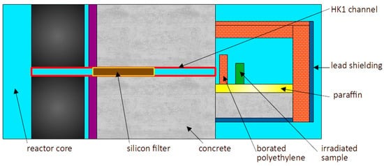
The scintillators were excited by exposure to gamma-ray radiation. The HK1 horizontal channel of the LVR-15 research reactor [
13] was used for the excitation of all tested scintillators. The channel is usually used for neutron radiography and experiments with irradiation in a thermal neutron field. The mixed gamma neutron field from the reactor core was filtered using a cylindrical silicon single crystal (diameter 78 mm, length 1000 mm), which was inserted into the channel as a neutron filter to suppress fast neutrons [
14]. At the output of the channel, 3% borated polyethylene bricks were used for thermal neutron shielding (see
Figure 1). In this shielding configuration, the neutron radiation is substantially suppressed, and the neutron/gamma fluence rate ratio is less than 10
−4 in the sample position. Prompt gamma radiation from the neutron reactions in the shielding also contributed to the gamma radiation at the sample position. Then, the scintillator samples were mainly irradiated by gamma radiation with a dose rate in the air of about 200 mGy/h. This value was measured with the thermoluminescent dosimeter. Gamma radiation energies are mainly in the range of 0.1 MeV to 1.5 MeV; a more detailed energy spectrum cannot simply be measured for this high dose rate.
The scintillators were irradiated for 10 min, and then the sample received a dose DIrr of about 33 mGy.
During irradiation, the scintillator sample was fixed in a lightproof detection unit, the same for all tested samples. When irradiation was complete, the detection unit was moved to the laboratory, which had a background dose rate of about 100 nGy/h. The detection unit was adapted for measurement in the current mode. A PMT (Hamamatsu Photonocs, Shizuoka, Japan, type R3998-02) was used for the detection of light emission from the scintillators. During the irradiation, part of the detection unit with PMT was irradiated. A picoammeter (Keithley Instruments, Solon, USA, type 6517A Electrometer) measured the PMT anode current. The experimental equipment also included an HV source and a PC; see
Figure 2 and
Figure 3. Anode current measurement began about 100 s after the end of irradiation and continued for at least 1 day, and for scintillators with a longer afterglow, up to 7 days.
The sample was in optical contact with the head of the photomultiplier tube, covered with aluminum foil as a light reflector, with the exception of LiI(Eu) and NaI(Tl), which were encapsulated. In the case of CsI(Tl) with a 50 mm diameter, aluminum foil was used on all surfaces except 28 mm diameter for optical contact with PMT. The temperature during measurements was 22 °C ± 3 °C.
The measured time dependence of anode current
Ia(
t) should take the following general form:
where Ia is the anode current, t is the time from the end of irradiation, Idc is the dark current of the PMT, Ibgr is the current that corresponds to the background radiation, In are the currents that correspond to the components of the afterglow signal at t = 0, N is the number of afterglow components, and τn are the relevant decay times.
3. Results
According to the procedure described above, afterglow measurements were made for the scintillator samples listed in
Table 1. Measurements of the anode current, using the picoammeter, were noted and saved, with a sampling time of 1.6 s. A detection unit without a scintillator went through irradiation and measurement, and it was verified that the influence on
Ia of the other parts of the detection unit was negligible.
As an example, a comparison of measured and fitted data on the anode current
Ia for the NaI(Tl) scintillator afterglow measurements is given in
Figure 4. The resulting fitted time dependence currents
Ia for the seven scintillators are in
Figure 5.
As the various scintillator samples have different dimensions, luminescence efficiencies, etc., the data were normalized to the same dose rate background value, which was about 100 nSv/h at the measuring point, with data more suitable for comparisons. After subtraction of the dark current
Idc and the background current
Ibgr and using
An =
In/
Ibgr, the formula for normalized value
Ra(
t) is given in Formula (1):
As the value of the background current was relatively stable for all samples, the function
Ra(
t) converges to zero after a sufficiently long period of time. Parameters
An and
τn can be gained through
Ra(
t) curve fitting. The weighted least squares method was used for the fitting, and Excel Solver was used to find the minimum variance. Weights were inversely proportional to the square of standard deviations, which were for individual points estimated from experimentally measured deviations and theoretical estimation. The range of measurable
τn corresponds to the time range of measurement, i.e., from tens of seconds to days. Regression analysis indicated that for all the scintillators studied, the afterglow curves can be approximated by a maximum of three decay components (for
N ≤ 3 in Formula (2)). The time dependencies from Formula (2) showed good agreement between the curve fitted and measured values; the typical deviation was 5%, lower for shorter times and greater for longer times. The resultant parameters
An and
τn are shown in
Table 2, where the values should only be interpreted as fitted parameters that do not always precisely correspond to the real decay components, e.g., more decay components with near decay times can be approximated with only one decay component. When every component corresponds only to one trap, decay time uncertainties can be estimated from 3% to 12%, depending on component number and amplitude value. The table shows that for the curve fitting of the CdWO
4 scintillator, only one decay component is sufficient; for CaF
2(Eu), LiI(Eu), and plastic scintillator, two decay components are required; and for BGO, CsI(Tl), and NaI(Tl), three are required. Trying the next decay component during the regression resulted in a statistically insignificant decrease in the variance (lower than 20%). An example in
Figure 4 illustrates the regression for the NaI(Tl) scintillator, where three decay components were used.
The afterglow decay curves are shown in
Figure 6. For a given scintillator, typical uncertainties comprising the statistical character of the signal and fitting uncertainty are estimated to be about 10%. For a comparison of the different scintillator types, significantly greater uncertainties may arise due to the different dimensions of the scintillators, the luminescence efficiency, etc.
The afterglow signal was measurable up to a value of about 10% of the background signal. Then, for the corresponding time
t0.1, it obeys
Ra(
t0.1) = 0.1, and this value can characterize the afterglow duration. The values of
t0.1γ are shown in the second column of
Table 3. The third column of the table lists the
t0.1UV values after UV excitation, provided for comparison purposes. Source data for UV excitation were taken from [
12], where
Ra values were gained in the same way, i.e., the ratio of afterglow signal to background signal. Using this ratio partly eliminates the influence of different scintillator types and dimensions. But a value comparable to the gamma irradiation dose cannot be given for UV irradiation.
The next item for comparison is the area under the afterglow curve, which corresponds to the apparent dose taken from the afterglow signal beginning at 100 s after the end of irradiation. Using a background dose rate of d
Dbgr/d
t = 100 nGy/h, the afterglow apparent dose
Da can be defined as
The values of
Daγ and
DaUV can be found in the fourth and fifth columns of
Table 3. In the last column, ratios of apparent dose from gamma irradiation
Daγ and irradiation dose
DIrr are given. The ratios show that the afterglow apparent dose is much lower than the gamma irradiation dose for all tested scintillators, as was supposed.
A comparison of the afterglow decay curves for gamma and UV excitation for the individual scintillator types is given in
Figure 7.
4. Discussions and Conclusions
The presented study of long-term afterglow for seven types of scintillators demonstrated, as predicted, that there were large differences between the types. The description of the afterglow curves for each scintillator required up to three decay components. The scintillators used can be roughly divided into three groups: the CdWO4 and plastic scintillator have a low level of long-term afterglow, CaF2(Eu) and LiI(Eu) come in the middle, and the BGO, NaI(Tl), and CsI(Tl) exhibit high levels of afterglow.
The CsI(Tl) scintillator is often used for X-ray radiography in the current mode, and its high long afterglow is a problem mainly for imaging changes during the time. The NaI(Tl) is used mainly for gamma spectrometry, where high long afterglow is usually no problem; deterioration of energy resolution can appear only in higher gamma radiation. The LiI(Eu) scintillator is used in pulse mode for thermal neutron detection, where afterglow is no problem. Using the current mode is possible here but not registered in the literature. The CaF2(Eu) and plastic scintillator are often used for X-ray and charged particle detection; their low afterglow is an advantage in current mode measurement. CdWO4 and BGO are scintillators with high density and a high effective atomic number; therefore, they are used mainly for gamma radiation with higher energy. They scintillate without an activator, and according to the literature, this is the reason for the low afterglow. But our results confirmed it only for the CdWO4, and the BGO has a high afterglow; after two days, it even has the highest afterglow of the studied scintillators. Then, for current mode measurement, choosing between CdWO4 and the BGO, the first one is the better option.
The afterglow parameters of a given scintillation material depend on many parameters, such as irradiation time, temperature, and form of excitation radiation. In this study, a comparison with older measurements where the excitation came from UV light instead of gamma radiation is provided. To allow a comparison of the results of gamma and UV excitation, it is necessary to consider that the UV irradiation “dose” cannot be evaluated as simply as that from gamma excitation. For some scintillators, especially for CdWO4, differences in the results for the two types of excitations are very significant, which was expected due to quite different types of excitations. The reason is not precisely known; it can be in different energies of excited electrons or holes and consecutively different catching in individual traps or in higher self-absorption of UV radiation in the samples compared with gamma radiation self-absorption. But for CsI(Tl) and NaI(Tl), the gamma and UV results are quite close in shape, as well as for the Ra(t) value. The reason for the two scintillator types can be in the random coincidence or in the full trap saturation with both forms of excitation.
The results can be helpful in theoretical research into scintillator long-term afterglow. The results should also serve to inform scintillator choice for some radiation detection applications.