1. Introduction
In the present context, the multilevel inverter (MLI) is widely used in the industry in order to obtain a power output with low THD. Generally, configuration of the MLI can be classified as symmetrical or asymmetrical. Symmetrical configuration of the MLI has many disadvantages, i.e., requirement of a large number of switches, low voltage levels, high THD, high conversion loss and low efficiency. However, asymmetrical MLI structure offers high efficiency, low conversion loss and low THD, with fewer switches to make more steps in the output voltage [
1,
2,
3,
4,
5,
6].
Foti et al. [
7] proposed an asymmetric hybrid multilevel inverter (AHMLI) used for motor drives, and photo voltaic (PV) for fast and precise regulation. They obtained low-order current harmonic in grid current lower than 2%. THD in the primary voltage of transformer and grid current without harmonics compensation was estimated as 5.2% and 10.9%, respectively. These values are reduced to 2.9% and 11.9%, respectively, with power filter function.
Sarwer et al. [
8] proposed a new design of the asymmetrical MLI to make 15 steps in the load voltage using NLC. Different losses of the inverter were also investigated by using PLECS software, and thermal modeling of the IGBT switch was performed. They proposed an MLI using simulation parameters, i.e., an output frequency of 50 Hz, R load of 50 Ω and 100 Ω and L load of 250 mH. The THD in the load voltage was evaluated as 5.5% for the RL circuit. The maximum efficiency of the converter was calculated to be 98.6%. Thakre et al. [
9] tested the performance of a 15-level inverter for different ranges of switching frequency. The inverter consisted of 12 MOSFET switches, and an 18 Ω + 25 mH load was considered. The voltage THD was measured as 4.25%, 3.45%, 2.59% and 2.15% for 15, 17, 23 and 31 voltage steps, respectively.
Chattopadhyay and Chakraborty [
10] introduced an asymmetrical cascade topology with the aim of increasing the number of levels in a power system. They achieved this through the level doubling method, which incorporated floating capacitors. The result of this topology reduced the auxiliary source nearly 66% and obtained a 65-level inverter, with 12 switches required per phase to achieve high-resolution output voltage.
Karri et al. [
11] proposed a symmetrical and asymmetrical configuration to obtain seven steps, nine steps and eleven steps in the load voltage. They compared the blocking voltage and cost function of the MLI with the latest topologies in this area. They tested the developed hardware for various operating conditions. Singh et al. [
12] analyzed a reduced-switch nine-level MLI with a single source to generate all levels of voltage. They employed the carrier PWM method in the MLI to estimate the harmonics using a MATLAB/Simulink environment.
Kurdkandi [
13] developed a transformer-less inverter to supply the unity and non-unity power factor loads. A controller was designed to produce the different pulses and to control active and reactive power between inverter and load. Percentage harmonic in the load voltage and output current were estimated to be 25.65% and 1.51%, respectively, for a load of 0.77 kW. Choudhary et al. [
14] designed a 17-level inverter using a switched capacitor to obtain high gain. They employed the series and parallel combination of capacitors for the automatic balance of voltage with input voltage source. They minimized the inrush current of the capacitor by using soft switching. THD values in the voltage without and with induction were estimated as 4.73% and 4.03%, respectively.
Bana et al. [
15] investigated the performance evaluation of a 3.9 kW solar-PV-coupled 17-level inverter using carrier-based PWM and SHE modulation schemes. They tested the inverter for step variation in solar radiation, rapid changes in load, frequency variation and changes in modulation index. The harmonic spectrum in the output voltage was estimated as 3.88% and 2.18% for the PWM and SHE modulation schemes, respectively.
Hussain et al. [
16] developed a 15-level switched-capacitor-based MLI with self-balancing property of capacitor. The designed inverter offered the maximum efficiency of 96.33% with THD of 7.82%. They tested the waveform of load voltage and current under sudden change in the load from 0 to 150 ohm + 120 mH to a load of 75 ohms and 150 ohm + 120 mH to a load of 150 ohms, respectively. Fahad et al. [
17] demonstrated the working of the 15-level MLI to minimize the THD and cost with the increase in system efficiency. The harmonic spectrum of load voltage and load current were determined to be 5.50% and 3.26%, respectively. They tested the different output waveforms of the MLI for the modulation indexes of 0.2 to 1.
Based on the review of papers, it is noticed that most of the researchers have not compared the performance parameters of the AMLI with different modulation techniques. Further, the effect of changes of modulation index, frequency and load change on the levels in the load voltage was not analyzed. Also, efficiency and losses of AMLI were not estimated for the variation in modulation indexes [
11,
12,
13,
14,
15,
16,
17,
18,
19,
20].
This paper proposes an asymmetrical MLI structure with minimum switches to produce seven and fifteen steps in the load voltage. As per the requirement, expansion of the considered MLI configuration can be made to obtain more levels of voltage with the built-in capability to obtain both positive and negative levels. Further, different modulation techniques, i.e., SPWM, SHEPWM and NLC, are used to generate pulses for different switches of the inverter. Performance parameters of the inverter have been determined with various modulation techniques. Parameters, i.e., number of levels, THD, losses, power delivery and efficiency, are considered in the paper. Inverter operation is also verified for change in load and modulation indexes.
Section-wise organization of the paper is summarized as follows. Structure of the considered topology of the AMLI is discussed in
Section 2. The methodology of different modulation techniques, i.e., SPWM, NLC and SHEPWM, is given in
Section 3. Gate pulses of different switches for SPWM, NLC and SHEPWM methods are discussed in
Section 4.
Section 5 describes the mathematical model for the loss analysis of the AMLI. Finally, different results of the system simulation and system hardware test bench are obtained and discussed in
Section 6.
2. Asymmetrical MLI Topology
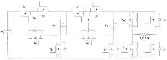
A simple unit of the considered novel modular AMLI topology is depicted in
Figure 1. The AMLI structure uses twelve MOSFET switches, three sources and ten driver circuits to achieve fifteen levels in the load voltage. This topology can be modified as cascaded connection of basic modules to attain more steps in the load voltage. A higher number of levels may be useful in electric vehicles, pumps, compressors, conveyors and DC transmission applications.
Different switching patterns of the 15-level inverter topology are summarized in
Table 1. Switches S
7 and S
8 or S
9 and S
10 are required in the ON state simultaneously to obtain zero load voltage, while switches S
1, S
7 and S
8 simultaneously can be turned on to achieve the first step of load voltage (+V
1). Different switching states for obtaining other steps of the load voltage, i.e.,
(V
1 + V
2 + V
3),
V
3,
(V
2 + V
3),
(V
1 + V
3),
(V
1 + V
2),
V
1 and
V
2, are also given in
Table 1. The magnitude of different DC supply is considered based on the load voltage.
Flow of current in the load can be estimated on the basis of the switching pattern of power switches. Further, all 15 voltage steps in the load can be achieved by using switching states as per
Table 1. It is always checked that flow of electric current follows a closed path and the other parts of the circuit are closed to avoid short circuit. Further, the remaining switches are turned off to obtain a uniform current flow.
Further, it has been noticed that the considered asymmetrical MLI topology is modular, and it is compared with the topologies reported in the literature on the basis of requirement of voltage sources (N
VS), number of voltage steps (N
Step), number of switches (N
Swi), number of driver circuits (N
Dri), number of on-state switches (N
On-swi), etc., as given in
Table 2. It has been observed that the proposed topology of inverter requires a smaller number of switches and driver circuits to obtain 15 voltage steps across the load. The number of switches per voltage level is also lower compared to other configurations reported in the literature. Also, fewer gate driver circuits are required for switches in the proposed topology.
6. Simulation and Experimental Results
Simulation of the considered AMLI has been carried out in MATLAB/Simulink 2019a to obtain 15 voltage steps. Modulation methods, i.e., SPWM, SHEPWM and NLC, are used for the operation of the considered AMLI in the present work. Different AMLI performance parameters are monitored and assessed for several real-time conditions, i.e., voltage steps, frequency change, variation in modulation index, total losses, harmonic spectrum, conduction losses and switching losses are determined.
An experimental test bench of the considered AMLI is developed as presented in
Figure 7. Different components have been used in the hardware development of the AMLI, which include MOSFET, driver circuit, current sensor, voltage sensor, DSO, quality analyzer, optocoupler, etc. A summary of the brief specifications of these components is given in
Table 3. Simulated results have been further verified in hardware with an OPAL RT 4510 simulator and RL load. Opal RT generates the switching pulses for the inverter setup [
40,
41]. The same setup is used to verify the results of NLC, SHEPWM and SPWM modulation techniques. Due to the high-frequency limitation of the power quality analyzer (Fluke Power logger 1736), SPWM is tested at 2 kHz switching frequency.
A simulation of the 15-level AMLI is tested for different modulation techniques, and results are compared based on the voltage steps, current, THD, losses and efficiency. The DC voltage sources used in the 15-level modular AMLI are 400 V, 200 V and 100 V, with a peak voltage value of 700 V. The inverter is tested under two test conditions with fixed RL load and sampling time of 10 micro-seconds:
- (a)
Effect of frequency variation: 50–100 Hz
- (b)
Effect of variation of modulation index: 0.4, 0.6 and 0.8.
In the first case, the effect of frequency fluctuation, i.e., 50 Hz to 100 Hz, is analyzed. In the simulation results, it is found that there is no change in the steps or level of load voltage for varying frequency with the NLC, SHEPWM and SPWM modulation techniques. Further, simulation results of the 15-level inverter with variable frequency for NLC, SHEPWM and SPWM are verified by the results on the experimental hardware setup, as clearly visible in
Figure 8,
Figure 9 and
Figure 10, respectively. Therefore, performance of the inverter is found satisfactory for the change in operating frequency.
In the second case, steps in the output waveforms of the 15-level inverter are tested for distinct values of modulation indexes with NLC, SHEPWM and SPWM modulation techniques. It is found that different levels are achieved with modulation techniques for the same value of modulation index.
For the modulation index of 0.4, the SPWM, SHEPWM and NLC modulation techniques produce seven levels, nine levels and seven levels in the load voltage, respectively. Eleven, fifteen and nine levels are produced with the SPWM, SHEPWM and NLC methods for Mi = 0.6. Further, analysis is performed to obtain 15 steps in the load voltage for different switching methods. It has been observed that 15 levels are achieved in the load voltage with SPWM, SHEPWM and NLC methods for the modulation index of 0.90, 0.80 and 0.95, respectively. Different simulation and hardware results of the inverter with the SPWN, SHEPWM and NLC modulation techniques for various modulation indexes are shown in
Figure 11.
Further, the load on the considered MLI has been varied from 25
0 mH to 50
0 mH to test the performance of the system for Mi = 0.80. The output load voltage waveform and current waveform under dynamic change in load are depicted in
Figure 12. It has been found that the considered system shows the stable operation under varying load conditions both in simulation and the experimental hardware test bench. Also, the experimental test results match with the simulation results.
Furthermore, power loss analysis of the AMLI has been carried out to compute the conduction losses, switching losses and total losses with the considered switching methods. Accordingly, the efficiency and total load power of the AMLI are estimated for different Mi values from 0.1 to 0.9, as visible in
Figure 13. It is perceived that the SHEPWM method offers the highest efficiency of 97.40% while delivering the output load power of 4.77 kW. Total losses are estimated as 125.58 W at Mi = 0.8. In total losses, the share of conduction loss (114.40 W) is greater than that of switching losses (11.18 W).
The efficiency and total losses of the AMLI with the SPWM method are obtained as 97.21% and 106.40 W, respectively, for Mi = 0.9. At this point, the AMLI delivers the load power of 3.71 kW to achieve the considered 15 levels. At Mi = 0.80, efficiency and total losses are estimated as 97.14% and 86.18 W, respectively, with 13 steps in the load voltage. Further, total losses and efficiency with the NLC technique are calculated at Mi = 0.9 as 105.88 W and 97.18%, respectively, to feed the load power of 3.65 kW. At Mi = 0.80, efficiency and total losses of the AMLI are estimated as 97.09% and 88.49 W, respectively. However, only 13 levels are achieved at Mi = 0.8 and Mi = 0.9. At Mi = 0.95, all 15 voltage steps are achieved with lesser efficiency.
The THD spectrum of the 15-level inverter model is measured through the FFT toolbox of MATLAB. Power logger (Fluke 1736) is used to estimate the harmonics of the experimental test bench. Further, the spectrum of harmonic voltages and fundamental voltage are collected for the SPWM, SHEPWM and NLC methods, as shown in
Figure 14. It is found that the value of THD in the load voltage is lower in the case of hardware setup in comparison with the simulation.
At Mi = 0.80, it is observed that SHEPWM offers the lowest THD of 5.45% and 5.10% on simulation and hardware setup, respectively, whereas THD in the load voltage with NLC and SPWM are estimated as 6.66% (Mi = 0.86) and 9.19% (Mi = 0.90), respectively, using the MATLAB simulation. In the AMLI hardware setup, NLC and SPWM offer a lower THD of 5.60% and 6.80%, respectively, as compared to the simulation.
Average power distribution of different voltage sources to meet the load has been estimated for the considered modulation techniques as reported in
Table 4. It has been noted that among three sources, voltage source V
3 delivers the highest power to meet the load, followed by voltage source V
2 and V
1. In the case of SHEPWM, the power distribution of voltage sources V
1, V
2 and V
3 as a percentage of load power is calculated as 62.41%, 26.68% and 12.84%, respectively. Power distributions of SPWM and NLC are also estimated as reported in
Table 4.
Finally, a comparison of different performance parameters of the AMLI with the considered modulation techniques is given in
Table 5. Performance parameters, i.e., conduction losses, number of voltage steps, total loss, effect of frequency deviation, switching losses and THD, are calculated and compared. It is found that the output waveform remains unchanged with the change in frequency in all methods. Among different methods, the SHEPWM technique gives the AMLI its highest efficiency of 97.40% to meet the load of 4.77 kW. Also, the minimum harmonics in the load voltage with SHEPWM is found to be 5.45% (simulation) and 4.4% (hardware). The value of the load current has been estimated as 9.11 A, 9.93 A and 9.17 A for the SPWM, SHEPWM and NLC methods, respectively.